Ever since [Douglas Engelbart] and his team came up with the computer mouse, hackers, makers, and engineers have been creating ways to change and improve the design. Even the original mouse was something of a hack, built form a block of wood, a button, and two encoder wheels. The wire exited toward the user’s wrist, making the device look like it had a tail. Even after all these years, folks are still working to make the perfect pointing device. This week’s Hacklet highlights some of the best mouse projects on Hackaday.io!
 We start with [s_sudhar] and ORB – A 3D gaming mouse. Orb uses accelerometers and gyros to track its location in 3D space. The popular MPU-6050 chip provides all the sensors to create an Inertial Measurement Unit (IMU). The controller is an Arduino Micro, which provides the USB interface to a PC with the help of Arduino’s MouseKeyboard library. Two micro switches handle button duties. The original Orb was built up in a cardboard box. [S_sudhar] created a more advanced version housed in a 3D printed sphere with two buttons. The translucent joint between the two halves of the sphere is just begging for some RGB LEDs. We can already see them flashing red when you’re getting shot in Team Fortress 2!
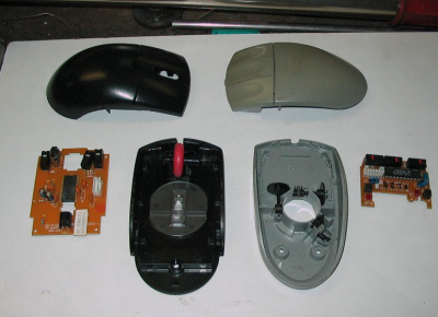 Anyone who has used X-Windows with a three button mouse knows how maddening the modern clickable center scroll wheel can be. You can’t click the wheel without it rolling, and causing all sorts of mayhem. There are plenty of software solutions and window manager mods to work around this, but [mclien] wanted a real three button mouse with a side scroll wheel. He didn’t want just any mouse though – it had to be a Silicon Graphics International (SGI) 3 button unit. His project 3-buttonmouse with seperate wheel used a dremel, drill press, and glue to transplant the electronics of a 3 button scrolling mouse into the classic SGI plastics. The final wheel placement did work – but it didn’t quite fit [mclien’s] hand. It did fit one of his friends hands perfectly though. So well in fact that the friend borrowed [mclien’s] creation. Neither the mouse nor the friend have been seen since!
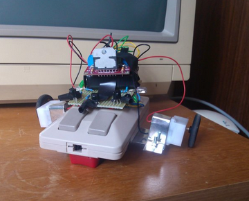 [Jay-t] decided that mice are for more than pointing, so he built Jimmy the mouse bot. Jimmy is a robot built from an old Commodore Amiga two button mouse. His brain is a Parallax Propeller processor. Two outrigger mounted gear motors help Jimmy drive around. Jimmy has plenty of sensors, including infrared object detectors, switches, and a GPS module from Adafruit. Jimmy may be the world’s first homing mousebot. [Jay-t] does all his interactive testing with Tachyon Forth on the Prop. The great thing about having an 8 core processor is that there is plenty of room for expansion. Even with all these sensors, Jimmy is still only using 3 cores!
Finally we at [Clovis Fritzen] and the Wireless Batteryless Mouse. This is our favorite type of project – the kind that has just been uploaded. [Clovis] plans to use a movement based system to charge up a supercapacitor – eliminating the need for batteries or wires. He’s also hoping to use an accelerometer to detect the mouse’s position rather than a power-hungry optical system. The details are still sparse, because he’s just started the project! These are exactly the type of projects that get us thinking. How will [Clovis] translate movement to energy? Will it be weights, like a self-winding watch? Maybe pizeo elements in the buttons. Will people mind having to jiggle their mouse to get it working once that capacitor is discharged? One thing we’re sure of, [Clovis] has a proven track record of implementing projects like his weather station. Get in there and help with your own ideas, or simply follow along with us and see how this one turns out.
Not satisfied? Want more mousy goodness? Check out our freshly minted mouse and pointer projects list!
That’s about all the time we have for this week’s Hacklet. As always, see you next week. Same hack time, same hack channel, bringing you the best of Hackaday.io!