[JBeale] squeezed every last drop of performance from a $5 Doppler radar module, and the secrets of that success are half hardware, half firmware, and all hack.
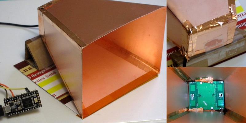
On the hardware side, the first prototype radar horn was made out of cardboard with aluminum foil taped around it. With the concept proven, [JBeale] made a second horn out of thin copper-clad sheets, but reports that the performance is just about the same. The other hardware hack was simply to tack a wire on the radar module’s analog output and add a simple op-amp gain stage, which extended the sensing range well beyond the ten feet or so that these things are usually used for.
With all that signal coming in, [JBeale] separates out the noise by taking an FFT of the Doppler frequency-shift signal. Figuring that people walk around 2.2 miles per hour, [JBeale] focuses on the corresponding 70 Hz frequency bin and finds that the radar will detect people out to 80 feet. Wow!
This trick of taking an el-cheapo radar unit and amplifying the signal to do something useful isn’t new to Hackaday. [Mathieu] did it with the very same HB-100 unit way back in 2013, and then again with a more modern CDM324 model. But [JBeale]’s hacked horn and clever backend processing push out the limits of what you can expect to do with these cheap units. Kudos.
[via PJRC]


I’ll have to comment on this: Ten years ago I pulled an old radar door opener from the trash pile of an 80’s super market. It was the old Gunn diode kind in an aluminium housing. I also wasn’t satisfied with its range of 30 so feet, so I made a proper horn feed for it and put it in the center of an offset tv dish. I also tapped the audio intermodulation frequency and routed it to an amp. I could hear a car 3/4 mile away and listen in on their car stereo 100 ft away because of the reverberating sheet metal cars are made off. Most interesting were joggers, They wear thin enough clothes and have less body fat so when they waited for the lights to change their pulse were clearly audible from 45 ft away, so I could easily access their physical shape by how fast their heart rate settled!! Another use was to “look” through walls. Pointing the dish on the building across the street, and moving it in increments, I could hear where there were occupied rooms with people, I have no idea how deep this sensing capability was, but I could detect people through walls where there no windows. I did try to integrate the audio output with a fourier transform filter and the some pattern recognition to automatically identify different targets, like a modern metal detector does, but my programming skill are much to be desired so that was only a partial success. I managed to distinguish between cyclists pedestrians and cars, but the quality of the signal was so high that it could have been used to recognise individuals.
Wow, and Damn….
Sounds legit
Your jaw-drop inducing description demands that you are urged to convert that research into a Hackaday’s “Assistive technologies” challenge project, for giving nearest thing to a long-range vision to the blind. That would make tremendous difference.
If you can’t make it this year, I am certain next one will have a similar challenge too.
That was truly describable as “Turn disability into this ability”.
nononoooo. weapon-ize! weapon-ize! yeh yeh heheh..
Currently the Gunn diode has a new life as an microwave field strength meter, which is much more useful to measure wifi transmit power ( most brands exaggerate their transmit power, or they rate their device based on what is leagal in thailand) If any of you want to make a long range intruder alarm, wildlife detector, or eavesdropping device, I got the info from this site: http://home.earthlink.net/~w6rmk/radar10g.htm
Also the ARRL handbook has plenty of info on antenna design and receivers for 10 GHZ.
thanks, that was a great read, once again the comment is much more interesting than the post itself :)
Anyway you could disassembly it and post schematics so that it can be recreated?
Very impressive results!
How big was the reflector dish? Do you know the frequency or the model for the sensor? Was the dish mobile, or on a fixture? Wasn’t it too sensitive to vibrations? Were those walls made out of concrete, or wooden walls? Do you have any other construction details, please? It would be a very interesting experiment to reproduce.
Added to the projects bucket list.
It was around 2 and 1/2 ft the beam was ouite narrow 4 degrees or something. Gain increases as frequency goes up so my 10mW Gunn diode made something like 1W EIRP, not something you point at a fighter jet on drill or an airport if you don’t want your shop raided. I used a tripod for a telescope and yes I had to sit still or my own steps would be picked up in the audio. Most houses are brick wall, i.e. two layers of wall with 4 inches of space in between for insulation. Similar devices are sold to the army for hundreds of thousands of dollars to detect ilegal combatants hiding in buildings, that’s pretty overpriced for something that in essence is a supermarket door opener attatched to a tvdish, but they are erringly sensitive devices. My reply above provides some details for info. Lots of X-band radio amatuer hacking and longrange comms were popular in the 80’s. Routinely 60 miles links were made line of sight between mountain tops.
Thank you!
This is great, we are really missing out in the hacking world on good radar units. What is needed is a good software controlled phased array antenna and better software to resolve the signals. That this module is built as a Doppler radar set means even more usability and filterability as we see in the post.
Starting with those we could begin have very useful 3D radar vision and eventually with more power and a completely new design even possibly something you could use from a low flying aircraft if configured as a beacon or transponder ping with callsign on amateur frequencies. Radar mapping would be very cool IMHO.
This is a damn good start though.
Moving on I read the following wikipedia articles which are actually a great intro to the topic
https://en.wikipedia.org/wiki/Active_electronically_scanned_array
https://en.wikipedia.org/wiki/Synthetic_aperture_radar
the electronically controlled phased array is a bit beyond me as i have little beyond theoretical understand of how to steer a beam with interference patterns in signals from multiple dipoles, but I think works by messing with signal delays and the bending or focusing as we see in Fresnels and Yaggi antennas. A cheap DDS for frequency hopping a few MOSFETs for power, the AESA antenna, and someone has to design a LNA receive stage which takes advantage of sampling over the time dimension to grab a pulsed signal return below the noise floor as well as DSP to put it all together into a useful live image or data in a way similar to a medical ultrasound scanner does. Keeping QRP in mind I bet we could have a really good useful radar usable even by aircraft for weather, mapping, maybe even scanning for other aircraft if we are in a Top GUn mood yet at signal power below what would get anyone in legal trouble, the military has been doing exactly this for a while on stealthy aircraft who have to bury their radar signal under the noise floor vs the old interceptors who just relied on banks of tubes for megawatt searchlight radar systems.
It looks like Infineon has 24GHz radar modules which costs as little as 3.38 USD in quantity of 3000 on Digikey, so if you can source them independently this gets into hacker budget range. I’m not sure if any of them has phase offset capability…
BTW, arrays only exhibit directional gain on Rx and not on Tx, so the low power operation of this system makes sense.
Maybe you are talking about this one? https://www.infineon.com/dgdl/Infineon-BGT24LTR11N16-DS-v01_01-EN.pdf Not bad, it’s a full 24 GHz transceiver on a chip. You would still need to make the external circuit board for it, which I think at 24 GHz is not trivial. The supercheap X-band HB100 has a magical-looking PCB under the shield can, full of microwave tricks. https://www.allaboutcircuits.com/news/teardown-tuesday-hb100-doppler-radar-module/
> BTW, arrays only exhibit directional gain on Rx and not on Tx
You’re gonna need some proof to back up that extraordinary claim.
https://en.wikipedia.org/wiki/Reciprocity_(electromagnetism)
> reciprocity implies that antennas work equally well as transmitters or receivers, and specifically that an antenna’s radiation and receiving patterns are identical
And here’s an animation of a phased array Tx displaying directionality: https://en.wikipedia.org/wiki/Phased_array#/media/File:Phasearray.gif
I didn’t apparently remember it completely correctly. What I said is relevant for sparse antenna arrays:
“Thus when the sources are farther than λ apart, all the constructive interference effects cancel on average – the total power emitted is then just the sum of the power begin emitted by the sources.”
– http://users.physics.harvard.edu/~schwartz/15cFiles/Lecture18-Antennas.pdf
But on reception, a bigger distance means more resolution, so there is a trade-off. I can’t find the original source I got this info from, but it also showed how you eventually end up with gaps in your radiation pattern.
My oh my.. Reminds me of a story my daughters first husband told, back around 1979 or so. It seems he was an IT guy for one of the military services, And he was irritated by the MPs with “Hand Held” radar guns, hiding behind buildings and writing speeding tickets on the base.. He cobbled up a high power amp and a home made antenna hooked to a radar frequency chip. The result was, blowing the “Hand Held” receiver into a smoking ruin. Now, as the story goes, this did not set well with the MPs, and resulted in a car by car search of the entire base. He was never discovered, so I’m assuming he never went to Leavenworth…
Unlikely. Jamming the radar gun is easy, but destroying the receiver requires a very high power density. Most radar guns use a Gunn diode (GD) coupled with a mixer diode (MD) right in front of it. The MD is already exposed to the a very strong EM field from the GD. This is what drives it strongly enough to make it self-mix the incoming signal to DC. The signal, coming from this transmitter and after path loss, would need to be at least 10-20dB stronger than the transmitted signal. This is unlikely, unless we are talking megawatt power levels or extremely short ranges.
I believe it was 1000 watts..
I was not there.. but it sounds about enough to do the job.
Sounds like enough to cook some gonads. Hope he doesn’t live near me.
Cataracts or GTFO. The gonads just get warm by the time you’re blind.
So what would it take with this setup to find the Dopplered return stripe on a waterfall audio display in order to scan for aircraft against a nice clean sky? I think it is more a matter of improving the RX signal considering I have made transatlantic transmissions on CW across the Pacific with a 3w QRP set on 40m and I know someone who did a moon bounce with WJST, time, and under 50w.
Secondly how do we play with the reflectors to switch focus between a big wide flood pattern or a tight spot?
I know you can play with antenna software to futz with the tightness of a beam but like myself most programs are designed for thinking big dipoles and Yaggi; not cavities, dishes, and waveguides.
Increase transmitter power and improve receiver sensitivity. Don’t forget that the echo power falls with r^4, in contrast to r^2 for normal non-reflected transmissions. A 10-20w transmitter coupled with a good receiver should be able to do it for a proof-of-concept with a nearby target.
Antenna gain is crucial, this is an almost free transmitter and receiver boost. Don’t settle for less than 30dBi. The higher the frequency the more gain you will get from an antenna of equal size, but the more difficult it becomes to build high performance RF circuits. With respect to available off-the-shelf components and HAM allocations I would try to for 5 or 10 GHz. Good, high-gain, dishes can be bought from the Wireless ISP market. You can get them very cheaply second-hand, just look for one with a built-in radio that is either obsolete or broken. Then just add an SMA connector and you have a good antenna. High power can be obtained cheaply in the 5GHz band, you can buy surplus 7GHz satellite uplink amplifiers that can be re-tuned to 5GHz with some effort.
TX/RX isolation is very important. If you transmit short pulses (so the transmitter is off when the receiver needs to listen), you only need to take care that the receiver is not destroyed from the coupled TX power but it can be way way higher than when using for example FMCW.
Employ pulse compression. This gives a link budget increase at almost not extra cost. It is pure mathematics on a computer, only the TX needs a modulation capability.
I didn’t expect this to make Hackaday, but very interesting to see these comments esp. Tore Lund’s dish project. I was fascinated by how cheap these are units are now, some under $3. If anyone’s motivated to play with this, don’t overlook the slightly more expensive CDM324 at 24 GHz, a similar idea but even smaller, draws slightly less power and with the shorter wavelength, could be even more directional for a given size reflector. This http://www.limpkin.fr/index.php?post/2017/02/22/Making-the-Electronics-for-a-24GHz-Doppler-Motion-Sensor is a good read on that module. I have an old Dish Network 2′ dish saved up for a rainy day. I had been thinking recently if I had any problems to which that could be the solution.
The problem with CDM324 is that it’s not that stable.
It uses a simple microstrip resonator for the oscillator and is nowhere as stable as the DRO stabilized 10GHz HB100 modules.
I wish it ware as CDM324 would be an easy entry to the 24GHz band.
My CDM324 is still going strong, but a friend has had few units mysteriously die after some prolonged use, which is not that OK for a radar.
Good to know. After I blew up my CDM324 by applying +5V to the IF Out pin, I had a look inside: https://goo.gl/photos/ZZeaj7dLyfe7ahLo7 I’m curious what the larger square component is at left, is that the one active device? The resonator element is at upper left?
I wonder if the IF Out pin is connected to an extremely small-geometry diode of some kind, and is static-sensitive. And making it static-safe would require an extra $0.02 in parts which were left off due to cost.
It took me 2 years but I finally have a hotwheel radar gun.
I think I read a article in hackaday about it after I saw one at the used store.
It works great up to about half a mile. I’ve been trying to think of a project that I could use it in.
Any Ideas would be great.
Have you checked Ed Paradis web page?