It’s so easy and so cheap to order things like CNC routers and 3D-printers off the shelf that we can be forgiven for forgetting what was once involved in owning machines such as these. It used to be that you had no choice but to build your machine from the ground up. While that’s less true today, it’s still the case if you want to push the limits of what’s commercially available, and this huge scratch-built 3D-printer is a good example of that.
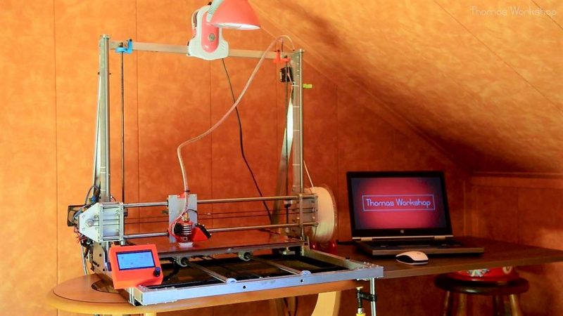
It’s not exactly a fresh build – [Thomas Workshop] posted this last year – but it escaped our notice at the time, and we think the three-part video series below that details the build deserves a look over. When we say scratch built, we mean it. This machine started off as a bundle of aluminum and steel stock. No 80/20 extrusions, no off-the-shelf linear rails – just metal and a plan. The build was helped considerably by a small CNC router, which also had that DIY look, but most of the parts were cut and finished with simple hand tools. The resulting gantry allows an enormous work volume 40 cm in each dimension, with a heated bed that uses four heat mats. We were impressed that [Thomas] got the build just far enough to print parts that were used to finish the build – that’s the hacker spirit.
It’s perhaps not the biggest 3D-printer we’ve seen – that distinction might go to this enormous 8-cubic foot machine – and it certainly can’t print a house. But it’s an impressive build that probably cost a whole lot less than a commercial machine of similar capacity, and it’s got that scratch-built cred.
Thanks to [Baldpower] for the tip.


nice build, i’m sure that making it was also much more fun then otherwise just ordering one.
looks slightly easier than building an anet a8 kit :)
-e did use square extrusions and off the shelf pulleys, idlers, smooth rods, motor mounts etc, imho not really a scratch build in the purest sence. But nothing wrong with that. I’m currently building a corexy 3d printer based on openbuilds 2020 profiles and wheels and cnc router machined parts, no 3d printed parts except the hot and cold end, I’ll use those from my old prusa i3 clone. The mechanics are done for the most part.
He didn’t start from a kit, nor did he start from anything that looked like the result. When you bake bread from scratch you don’t grow and mill your own flour, why would we redefine “from scratch” from the established usage?
If you want to build something, anything, from scratch, you have to start by re-inventing the universe.
Likely the point is not to get a working printer, but to learn on how to build one and to have fun in doing all the handcrafting. That’s certainly a valid point.
And if you want to build everything, reinventing the universe is definitely the way to go.
+1
It’s a nice build, but there’s a lot of little cringes going on.
1) all his pillow blocks have one set screw squeezing the bearing on one point. This makes the bearing ever so slightly oval and they don’t run quite right, or at least as best as they could. A better design would be to split the pillow block and use the set screw to squeeze the two halves together again.
2) He puts all his trust on the frame being naturally square with little in terms of cross-members and supports, or any way to adjust anything. If you lean on it, it will put the guides into a skew, if they weren’t already because he seems to be just eyeballing where the mounting blocks are installed.
I’m willing to bet he’ll have geometry issues trying to print large objects.
Yep, I saw both of those. Also, SO many nuts inside tubes, many of which will eventually vibrate loose. Loctite is your friend.
I once made a miniature version of a similiar frame from 3mm RC car axles and used those little metal D pieces and screws from inside screw terminal blocks for the pillow blocks and runners, filled with soldering tin for a makeshift babbitt bearing.
I only got so far as making the X-Y table when it became painfully obvious that it’s never going to run right because at that scale everything has to be just so, and any twist or skew is going to bind the mechanism instantly. Since I did the same mistake of trusting the geometry to be square because it looks square and measures square, I didn’t put any adjustment screws in either and so the obvious happened.
Why don’t we see more 3D printer frames that are designed for alignment? (Or solid enough that it’s not relevant?) Designs like the Mendel 90 are more frame than printer, but for just that reason, they’re easier to align.
I say this as the proud owner of a still-skewed Prusa 2. Bringing triangles into square is just as much fun as it sounds, so it’s been limping along “good enough” for years b/c I just can’t be bothered.
All the designs I’ve seen treat the frame as an undesirable part of the build to be minimized. Compare to machine tools (and big woodworking tools) where the frame is what separates the good from the bad.
Good question. The design shown here goes back to the roots, and also goes back to the mistakes made back then.
Printer frames have to be stiff! There’s 1+ kg of print head which gets accelerated back and forth rapidly and almost no structure to respond to the resulting acceleration forces.
Mostly because rigidity costs money, and most 3d printing applications don’t need it nearly as much as say milling.
Good build. Fun to watch. Thx.
> It’s perhaps not the biggest 3D-printer we’ve seen – that distinction might go to this enormous 8-cubic foot machine
How quickly we forget!
https://hackaday.com/2014/09/20/nyc-makerfaire-a-really-really-big-printer/
https://hackaday.com/2015/03/27/wrapping-up-the-last-midwest-reprap-festival/
https://hackaday.com/2016/04/05/the-state-of-3d-printing-at-mrrf/
https://hackaday.com/2017/03/28/the-midwest-reprap-festival-spectacular/
I wouldn’t want to try a build like this, but it’s good to see some of the techniques used for making parts.
Nice build. I have a friend who needs a rectangular bed. I suggested he built his own 3D printer,
Lol I built mine out of wood using random bits and no planning, with drawer rails for linear motion. It worked very well when it wanted to. I kept it working long enough to build my new machine out of perspex monitor stands using the same electronics ( also using drawer sliders) that prints in multicolour. It also works well some of the time. Just has leveling issues and jams due to the nozzle being counterfeit. Here is a video on the new one https://youtu.be/HDPIE4vDStU, with a clip of the old one at the end. It took me 6 months on and off to get the first working… I should have bought a kit.