While the Bus Pirate 5 is an impressive piece of hardware, the software is arguably where the project really shines. Creator [Ian Lesnet] and several members of the community are constantly working to add new features and capabilities to the hardware hacking multi-tool, to the point that if your firmware is more than a few days old there’s an excellent chance there’s a fresher build available for you to try out.
One of the biggest additions from the last week or so of development has been the I2C sniffer — a valuable tool for troubleshooting or reverse engineering devices using the popular communications protocol. [Ian] has posted a brief demo video of it in action.
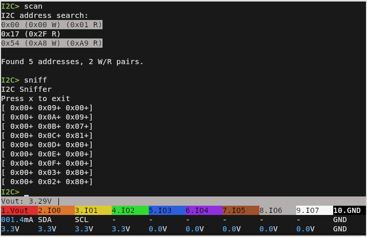
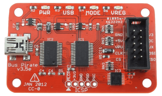
It’s actually a capability that was available in the “classic” versions of the Bus Pirate, but rather than porting the feature over from the old firmware, [Ian] decided to fold the MIT licensed pico_i2c_sniffer from [Juan Schiavoni] into the new codebase. Thanks to the RP2040’s PIO, the sniffer works at up to 500 kHz, significantly outperforming its predecessor.
Admittedly, I2C sniffing isn’t anything you couldn’t do with a cheap logic analyzer. But that means dealing with captures and making sure the protocol decoder is setup properly, among other bits of software tedium. In comparison, once you start the sniffer program on the Bus Pirate 5, I2C data will be dumped out to the terminal in real-time for as long as you care to see it. For reverse engineering, it’s also very easy to move quickly from sniffing I2C packets to replaying or modifying them within the Bus Pirate’s interface.
If you already have a Bus Pirate 5, all you need to do is flash the latest firmware from the automated build system, and get sniffing. On the fence about picking one up? Perhaps our hands-on review will help change your mind.