We’ve seen a growing number of posts and recommendations around the net regarding components, specifically transistors. “Don’t use old parts” they cry, “Go with newer components.” You can often find these recommendations on Arduino forums. This all came to a head with a page called “Do Not TIP,” which was linked in the Arduino subreddit. This page belongs to [Tom Jennings], creator of Fidonet, and one of the early authors of what would become Phoenix BIOS. [Tom] and a few others have been calling for everyone to send their old parts to the landfill – not use them, nor gift them to new experimenters. Get them out of the food chain. No offense to [Tom], but we have to disagree. These parts are still perfectly usable for experienced designers, and have a lot to offer new hardware hackers.
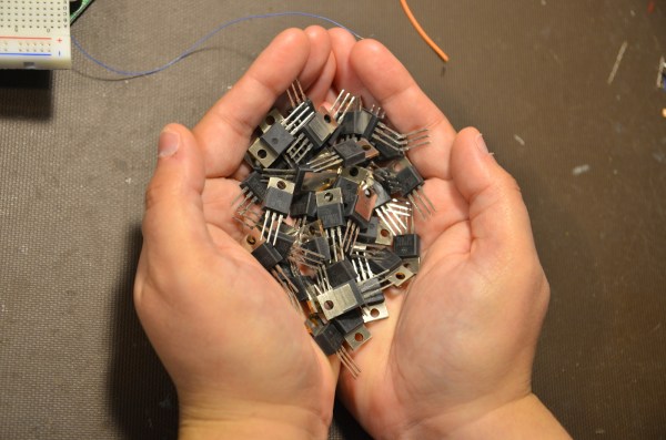
TIP is the part number prefix for a series of power transistors created by Texas Instruments. In fact, “TIP” stands for Texas Instruments Power. The series was originally released in 1969. Yes, that’s right, 1969. Why are we still using parts designed when man first walked on the moon? The same reason people are still using the 555 timer: they’re simple, they’re easily available, they’re robust, and most of all, they get the job done. The TIP series has been used in thousands of classes, tutorials both online and off, and millions of projects over the years. Much of that documentation is already out there on the internet. The TIP series is also out in the distribution channel – they’ve been used for 40 years. Any retail shop that stocks a few electronics parts will have at least one of the TIP series.
The TIP series aren’t always the best transistors for the job. However, for most hobbyist-designed circuits, we don’t need the best performance, nor the best price – we’re going to use the parts we have on hand. There is always room to improve once you get the basic circuit working.
Continue reading “You Can Have My TIPs When You Pry Them From My Cold, Dead Hands”


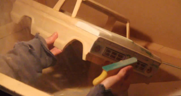
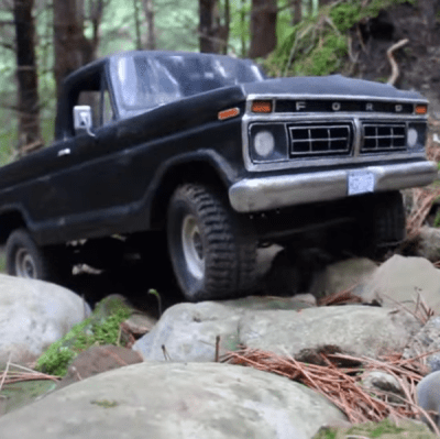 The build starts with the slab sides of the truck. The basic outline is cut into a piece of lumber which is then split with a handsaw to create a left and a right side. From there, [Headquake137’s] uses a Dremel to carve away anything that doesn’t look like a 1977 F100. He adds pieces of wood for the roof, hood, tailgate, and the rest of the major body panels. Small details like the grille and instrument panel are created with white polystyrene sheet, an easy to cut material often used by train and car modelers.