Adding PID Control To A Non-Adjustable Iron

Do remember your first soldering iron? We do. It plugged into the wall, and had no way to adjust the temperature. Most people call these kind of irons “fire starters.” Not only are they potentially unsafe (mainly because of the inadequate stand they come with) they can be hard to use, slow to heat up, and you never know what temperature you are soldering at.

[Mike Doughty] wondered if you could hack a cheap iron to be temperature controlled. He began by taking apart an iron, and adding a K-type thermocouple to the mica heating element with the help of a fiberglass sleeve. After a few tries at fitting and finding the right placement for the thermocouple, he then reassembled the iron, and attached everything to an off-the-shelf industrial PID controller.

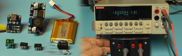
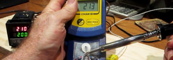
Not one to trust that everything was working, [Mike] began to test the iron. He used a Hakko FG-100 soldering iron tip thermometer to measure the “real” temperature of tip, and compared it to the value the K-type thermocouple was reporting it to be. The results were fairly impressive (as seen in the video after the break). Only about 10 degrees out. Not too shabby.

He concluded that although it did work, it wasn’t a replacement for a high quality soldering station. We suspect the real problem with this idea is that the mica heating element is way to slow to respond to any thermal load that the tip is given (but then neither did the unmodified iron.) If you’re interested in hacking together your own soldering station, you might be interested in the open source soldering iron driver.

[via Dangerousprototypes]

Continue reading “Adding PID Control To A Non-Adjustable Iron”

Workbench Eye Candy From Around The World

The workbench. We’re always looking for ways to make the most out of the tools we have, planning our next equipment purchase, all the while dealing with the (sometimes limited) space we’re allotted. Well, before you go off and build your perfect electronics lab, this forum thread on the EEVblog should be your first stop for some extended drooling research.

You’ll find a great discussion about everything from workbench height, size, organization, shelf depth, and lighting, with tons of photos to go with it. You’ll also get a chance to peek at how other people have set up their labs. (Warning, the thread is over 1000 posts long, so you might want to go grab a snack.)

We should stop for a moment and give a special note to those of you who are just beginning in electronics. You do not need to have a fancy setup to get started. Most of these well equipped labs is the result of being in the industry for years and years. Trust us when we say, you can get started in electronics with nothing more than your kitchen table, a few tools, and a few parts. All of us started that way. So don’t let anything you see here dissuade you from jumping in. As proof, we’ve seen some amazingly professional work being done with the most bare-bones of tools (and conversely, we seen some head-scratching projects by people with +$10,000 of dollars of equipment on their desk.)

Here’s some links that you might find handy when setting up a lab. [Kenneth Finnegan] has a great blog post on how his lab is equipped. And [Dave Jones] of the EEVblog has a video covering the basics. One of the beautiful things about getting started in electronics is that used and vintage equipment can really stretch your dollars when setting up a lab. So if you’re looking into some vintage gear, head on over to the Emperor of Test Equipment. Of course no thread about workbenches would be complete with out a mention of Jim Williams’ desk. We’ll leave the discussion about workbench cleanliness for the comments.

Build A Precision Voltage Reference Box

So you just scored a vintage piece of test gear, or maybe you just bought a fancy new DMM (Hmm…We love that new multimeter smell!) But can it read voltage accurately? How can you be sure? Well, that’s why you should build yourself a voltage reference box.

Youtuber [Scullcom’s] latest video has you covered. Wants some specs? Sure. How does a precision 10v and 5v output with only ±0.025% and an amazing 2.5ppm/°C sound? That’s very impress for something you can cobble together yourself.  We find it interesting that he actually uses some ebay parts to pull off this build. The LiPo battery, USB LiPo charging circuit, and boost regulator are all sourced from ebay. Not to worry though, as these parts are only used to supply power to a 15 volt linear regulator. The real magic happens in the Texas Instruments REF102 precision voltage reference. You give it a decently clean 12-36 volts, and it will give you a 10 volt reference out.  These amazing chips are able to obtain such precision in part because they are calibrated (or more specifically “laser trimmed”) from the factory. A secondary output of 5 volt is achieved by using a differential amplifier.

Warning: The video after the break is a bit on the long side(43 mins), so you might want to make some popcorn. But we find [Scullcom’s] teaching style to be lovely, and he does a wonderful job of explaining the project start to finish, soup to nuts. Continue reading “Build A Precision Voltage Reference Box”

Mini Robot Wars Looks Fun And Only Slightly Scary

“Ahhhh! They’re so cute! Wait a second, does that little robot have a spinning blade of death?!?!?”  Yes, yes it does.

Welcome to Bristol University 2nd Annual Robot Wars Tournament. It’s loosely based on the old BBC show Robot Wars, where contestants would design and build fighting robots. This pint-sized version is just down right fun to watch. But don’t let their size fool you, some of these little bots pack a mean punch.

This competition follows the “Antweight World Series Rules” and must fit inside a 4 inch cube with a max weight of 150 grams. There are some not-so-fun rules attached to that, such as “No flame based weapons” and “no use of electricity as a weapon.” But hey, it still looks like a blast.

We can’t help but to think that a contest like this would be an amazing thing for local hacker spaces to set up and organize. The playing field seems to be a reasonable size, such that it could be set-up and torn-down without too much hassle. And with RC transmitters/receivers available so inexpensively these days, and ebay flooded with little robot parts from China, now seems like a perfect time to start a local robot competition. It might be a great way to draw people into making and hacking. You can watch the video of the competition and meet the makers after the break.

Continue reading “Mini Robot Wars Looks Fun And Only Slightly Scary”

Happy Pi Day. 3.14159265359……

Unless you were alive in 1592, this is the closest to the perfect “Pi day” you’ll ever get.  3/14/15.  And if you want to take a moment to pause at 9:26:53 (am or pm?  Time zone? Country?) we’ll be right there with you. Well, sorta of.

Now, before you laugh, and think Pi is just a number, think again.  It’s almost magical in nature.  It’s effects on our daily lives is found everywhere.  From biology to astrophysics.  In the perspective of history, it can be used as a milestone to mark many different culture’s advancement of math and science.  In short, Pi is a keystone of the modern world.  With out it, we’d never would have gone to the moon. We might sill be on horse back.  And forget electronics.  That fun stuff never would have happened.

(As a side note, on this day, 3/14,  just happens to be Albert Einstein birthday.  Happy birthday!)

We hope you have an awesome Pi day.  We would love to see you in the comments too.  For example, we’d love to hear about and see posts of algorithms that can compute Pi.  How far can you compute Pi on a Raspberry Pi?  Or even child hood stories of your first encounter with that magical number.  Post up, and let us know your thoughts.

We’ll leave you with this cute video after the break, It’s an 8-year-old reciting 200 digits of Pi .  But if you need more digits….There is 1 million digits of pi.

Continue reading “Happy Pi Day. 3.14159265359……”

How To Identify Plastics Before Laser Cutting Them

If you own a pickup truck, you’ll quickly find yourself making friends with people who just happen to need help moving next weekend. Trust me, it’s almost magical. And if you own a laser cutter (or work in a hacker/maker space that has one) you’ll get some odd requests to cut or engrave plastic items of unknown type. Before you do, you should read this (pdf) chemistry lab written by [David A. Katz] to learn how to identify what type of plastic it is.

There are several reasons why you don’t want to cut or engrave some types of materials. A few make a gooey mess that you’ll regret even trying. Others make a horrendous odor. Some hackerspaces will even charge you extra if you stink up the place (aka: malodorous material charge.) Some tend to catch on fire. Yikes.

But that’s not the worst of it. Some types of plastic release potentially deadly hydrogen chloride gas. It’s bad for the optics, it’s wreaks havoc on the electronics and mechanics of the machine, and could do a really good job of messing up your lungs forever. In the video after the break, you can see the flame test for such plastics in action at the NYC Resistor as they test several common items using nothing more than a blow torch and some copper wire. In short, if the flame test produces a green flame, do not put it in the laser.

If you want to see a good list of what is and what isn’t ok to cut, head on over to ATXHackerspace’s wiki. They will give you a nice run down with lots of notes and helpful hints as well.

Continue reading “How To Identify Plastics Before Laser Cutting Them”

Design In Package Flexibility Into Your Next PCB

To err is human.  And to order the wrong component foot print is just part of engineering. It happens to us all; You’re working hard to finish a design, you have PCBs on the way and you’re putting in your order into your favorite parts supplier. It’s late, and you’re tired. You hit submit, and breathe a sigh of relief. Little do you know that in about a week when everything arrives, that you’ll have ordered the wrong component package for your design.

Well, fear not. [David Cook] has a solution that could save your bacon. He shows you how to design multiple footprints into your board to avoid the most common mistakes such as voltage regulators with different pin-outs than expected. Other uses for the trick include, common trim pots with different pin spacing and a layout for decoupling caps that will fit both a 0.1″ and 0.2″ footprints.

We’ll file this under the “Why Didn’t I Think of That” category. It’s a super simple hack, but that’s what we love about it. We could see this being very handy for people who often scavenge parts. Also, for makers that sell just a bare PCBs (without parts) to those that want just a board. No, it won’t save you if your need an SMD and you mistakenly ordered a dip, but at the end of the day, it’s a nice trick to keep up your sleeve.  You might never know when you’ll need it.