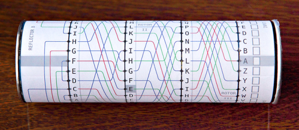
Broken RC Car Goes Online

When the remote for your son’s RC car goes missing, what are you going to do? Throw away a perfectly good robot chassis? No, we wouldn’t either. And these days, with WiFi-enabled microcontroller boards so readily available, it’s almost easier to network the thing than it would be to re-establish radio control. So that’s just what [Stian Søreng] did.

Naturally, there’s an ESP8266 board at the heart of this hack, a WeMos D1 to be specific. [Stian] had played with cheap remote-controlled cars enough to be already familiar with the pinout of the RC IC, so he could simply hook up some GPIOs from the WeMos board to the pins and the brain transplant was complete.

On the software side, he implemented control over TCP by sending the characters “F”, “B”, “L”, or “R” to send the car forward, back, left, or right. Lowercase versions of the same letters turns that function off. He then wrote some client software in Qt that sends the right letters. He says that response time is around 150-250 ms, but that it works for his driving style — crashing. (We’d work on that.)

Anyway, it’s a fun and fairly quick project, and it re-uses something that was destined for the junk heap anyway, so it’s a strict win. The next steps are fairly open. With computer control of the car, he could do anything. What would you do next?

Thanks [Eyewind] for the tip!

EKG Business Card Warms Our Hearts

Giving out a paper business card is so 1960s. Giving out a PCB business card, well that gets you up to the early 2010s. If you really want to stand out these days, give them a fully-functional EKG in a business card. (Note: works best if you’re leading an open-source electrocardiography project.)

Looking through the schematics (PDF), there’s not much to the card. At the center of everything is an ADuC7061, which is an ARM microprocessor equipped with 24-bit ADCs that also has an internal DAC-driven voltage reference connected to one of the user’s thumbs. This, plus a little buffering circuitry, seems to be enough to translate the tiny voltage potential difference across your two hands into a beautiful signal on the included OLED display. Very nice!

Everything (including the big version of their EKG) is open source and made on an open toolchain. If you’re interested in health and medical sensing, you should head over to the project’s GitHub and check it out. The standalone open EKG is based on a much more complicated circuit, and stands to be more accurate. But the business card version is just soooo cute!

Thanks [Ag Primatic] for the tip!

How Many LEDs Are Too Many?

“Should you answer a rhetorical question?” But anyway, the answer is that you can never have enough LEDs. At least that’s what [Adam Haile] at maniacallabs seems to think. So far, he’s up to 3,072.

We’ve reported on a previous big-LED build of [Adam]’s before, called the “Colossus”. And while this current display is physically smaller, it’s got a lot more LEDs. And that means a lot more, well, everything else. Weighing in at roughly 500W when full-on, with 175-part 3D printed frame and diffuser elements and driven by three Teensy 3.2 microcontrollers driving shift registers, this display is capable of putting out 60 frames per second of blinding RGB LED goodness.

The designs, adapter boards, and animation code will be posted once they’ve “had a chance to clean things up a little”. Here’s hoping that’s soon! [Edit: Code and designs are here. Thanks Adam!]

If you’re in the greater Washington DC area, you can even swing by the NoVA Maker Faire in Reston to check it out in person. If you do, tell ’em Hackaday sent you.

Continue reading “How Many LEDs Are Too Many?”

Telegram Your Devices

[Erhan] has been playing around with the Telegram instant messaging service. Initially, he worked out how to turn on and off LEDs from his cell phone: he sent commands from the phone through the Telegram bot API, to a computer that’s connected over serial to an MSP430 board that actually controlled the LEDs.

But that’s a little bit complicated. Better to cut out the middleman (err…microcontroller) and implement the Telegram reception and LED blinking on a Raspberry Pi. For a project that’s already using a Pi, using the instant messaging service’s resources is a very simple way to interface to a cellphone.

The code for both the standalone RPi project and the MSP430-based microcontroller application are available at [Erhan]’s GitHub. You’re going to be installing Node.js for their telegram-bot-api and jumping through the usual OAuth hoops to get your bot registered with Telegram. But once you’ve done that all on the Raspberry Pi (or target computer of your choice) it’s all just a few lines of fairly high-level code.

We’ve only seen one other Telegram application on Hackaday.io and we’re wondering why. It looks pretty slick, and with the bot’s ability to send a custom “keyboard” to the phone along with the message, it could make cell-phone-based control interfaces a cinch. Anyone else using Telegram for bots?

Embed With Elliot: March Makefile Madness

The make tool turns the big 4-0 next month, and we thought we’d start up the festivities early. In a two-part series, I’ll cover some of the make background that I think is particularly useful, and then focus on microcontroller-specific applications. If you’re still cut-and-pasting a general purpose makefile to run your toolchain, hopefully you’ll get enough insight here to start rolling your own. It can be a lot simpler than it appears!

Just as soon as the C programming language was invented, and projects started to get a little bit bigger than a “hello world”, it became obvious that some tool was needed to organize and automate compilation. After all, if you’ve got a program that’s spread over a number of files, modules, or libraries, it’s a hassle to have to re-compile them all any time you make a change to just a single section of code. If some parts haven’t changed, you’re just wasting time by re-compiling them. But who can keep track of all of this? Make can!

Continue reading “Embed With Elliot: March Makefile Madness”

Gigabit Ethernet Through The Air

There are a couple of really great things about transmitting data using light as the carrier. It can be focused so that it doesn’t spill all over the neighborhood like radio signals do — giving it both some security against eavesdropping and preventing one signal from stepping on another’s toes. And while you can modulate radio signals up nearly to the carrier frequency, the few gigahertz we normally use for radio just won’t cut it for really high bit rates. Light gets you terahertz.

The Koruza project is an open-source, “inexpensive” system that aims to transmit 1 Gb/sec over distances around 100 meters, using modulated infrared light. The intended use-case is urban building-to-building communication at speeds that would otherwise require laying fiber-optic cables. Indeed, the system piggy-backs on existing fiber-optic equipment to get the job done, but the hard part is aligning the units to get maximum signal from point A to point B.

koruza-spec-info

Koruza does this by including motorized lenses on the 3D-printed chassis. You make a rough alignment with a visible green laser, and then fine-tune the IR beams from a web console where you get immediate feedback on how the received signal strength is changing. Both Koruza boxes have a Raspberry Pi inside and use normal networking for calibration and signal-strength statistics. It’s a really neat system, and it’s fully DIY’able except for the commodity fiber-optic bits.

We’ve always had a soft-spot in our heart for transmitting data over light beams. The Ronja project has been doing so since 2001, and over longer distances, with completely DIY hardware, if at a slower bitrate. And now that Li-Fi seems to be getting traction, we might see an unfocused equivalent running inside our homes.

Thanks [Pavel] for the tip!

Does The World Need An FPGA Arduino?

What would you get it you mashed up an FPGA and an Arduino? An FPGA development board with far too few output pins? Or a board in the form-factor of Arduino that’s impossible to program?

Fortunately, the ICEZUM Alhambra looks like it’s avoided these pitfalls, at least for the most part. It’s based on the Lattice iCE40 FPGA, which we’ve covered previously a number of times because of its cheap development boards and open-source development flow. Indeed, we were wondering what the BQ folks were up to when they were working on an easy-to-use GUI for the FPGA family. Now we know — it’s the support software for an FPGA “Arduino”.

Icezum-rev1-1607-img1-peq_thumbnail

The Alhambra board itself looks to be Arduino-compatible, with the horrible gap between the rows on the left-hand-side and all, so it will work with your existing shields. But they’ve also doubled them with pinheaders in a more hacker-friendly layout: SVG — signal, voltage, ground. This is great for attaching small, powered sensors using a three-wire cable like the one that you use for servos. (Hackaday.io has two Arduino clones using SVG pinouts: in SMT and DIP formats.)

The iCE40 FPGA has 144 pins, so you’re probably asking yourself where they all end up, and frankly, so are we. There are eight user LEDs on the board, plus the 28 I/O pins that end in pinheaders. That leaves around a hundred potential I/Os unaccounted-for. One of the main attractions of FPGAs in our book is the tremendous availability of fast I/Os. Still, it’s more I/O than you get on a plain-vanilla Arduino, so we’re not complaining too loudly. Sometimes simplicity is a virtue. Everything’s up on GitHub, but not yet ported to KiCad, so you can tweak the hardware if you’ve got a copy of Altium.

We’ve been seeing FPGA projects popping up all over, and with the open-source toolchains making them more accessible, we wonder if they will get mainstreamed; the lure of reconfigurable hardware is just so strong. Putting an FPGA into an Arduino-compatible form-factor and backing it with an open GUI is an interesting idea. This project is clearly in its very early stages, but we can’t wait to see how it shakes out. If anyone gets their hands on these boards, let us know, OK?

Thanks [RS] for the tip!