The good part about FDM 3D printing is that there are so many different filament types and parameters to choose from. This is also the bad part, as it can often be hard to tell what impact a change has. Fortunately we got destructive testing to provide us with some information here. Case in point [Functional Print Friday] on YouTube recently testing out a few iterations of a replacement part for a car.
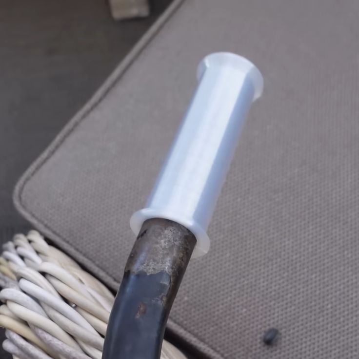
The original part was in ABS, printed horizontally in a Bambu Lab FDM printer, which had a protruding element snapped off while in use. In addition to printing a replacement in carbon fiber-reinforced nylon (PAHT-CF, i.e. PA12 instead of the typical PA6), the part was now also printed at a 45° angle. To compare it with the original ABS filament in a more favorable way, the same part was reprinted at the same angle in ABS.
Another change was to add a machine screw to the stop element of the part, which turned out to make a massive difference. Whereas the original horizontal ABS print failed early and cleanly on layer lines, the angled versions put up much more of a fight, with the machine screw-reinforced stop combined with the PA12 CF filament maxing out the first meter.
The take-away here appears to be that not only angles are good, but that adding a few strategic metal screws can do wonders, even if you’re not using a more exotic filament type.
Continue reading “Destructive Testing Of ABS And Carbon Fiber Nylon Parts”