Arduino Heart Rate Monitor

[Wolf] had a Polar brand exercise watch that wirelessly monitored a chest strap that sends it heart rate data. It sounds like there’s some way to transfer data from the watch to a computer, but it’s only meant for use with Polar’s website. He wanted to do a little more with the equipment so he ditched the watch and built an Arduino-based heart rate monitor.

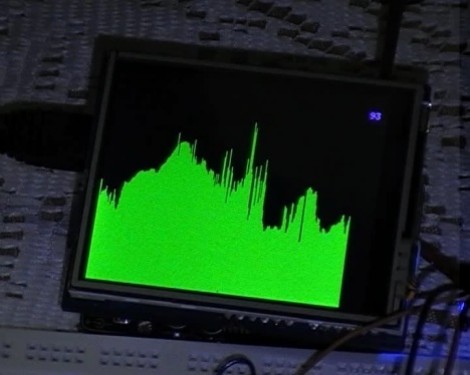
He’s still using the chest strap and was happy to find that SparkFun sells an OEM receiver for it. Just add a 32.768 kHz clock crystal and an optional antenna wire and you’re up and running. Once the receiver finds a transmitting chest strap, it will pulse an output pin with each beat of the heart. [Wolf] used the D2 pin of an Arduino Uno to connect to the receiver because this pin corresponds to one of the ATmega’s external interrupts. A rolling average of five inputs are used to help smooth the display data, which is shown on the 2.8″ LCD screen seen above.

Working With The µOLED-128-G1 Display

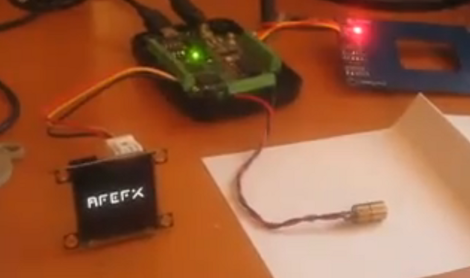
If you’re not already familiar with the 4D Systems µOLED-128-G1 display, [Gary] put together a project that shows some of the features it offers. This is a smart display, having its own onboard microcontroller and a microSD slot. The SD card stores image and video data, while the microcontroller takes care of displaying them based on simple serial commands it receives. This means you can hook it up to a computer or microcontroller and show still or animated sequences with minimal programming effort. We’ve embedded a video after the break, or you can look in on this slot machine project from last year that used the same module.

[Gary] is using a PIC microcontroller programmed with PIC Basic Pro. But most of the work is done with a 4D Systems program called Graphics Composer. You build out the images and animations you want to see on the screen, which are then formatted for the display and written to the SD card. [Gary] mentions that the card is not written using a traditional filesystem, so if you know of another way to write data to and from this card we’d love to hear about it in the comments. The image editing software will also spit out the serial commands necessary to pull your freshly minted graphics up on the display.

Continue reading “Working With The µOLED-128-G1 Display”

Discrete Logic Driving Game Development

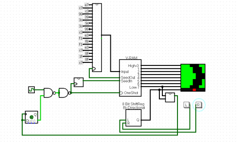
[Caleb] is hard at work on a driving game based on 7400 series logic chips. This will be his entry in the Open 7400 Logic Competition, and it really outlines why this contest is especially tricky.

The concept behind the game is quite simple. You’re the driver of a car (the red dot at the bottom of the display square seen above) and need to navigate the curves in the road as you drive along. It’s the same game as we saw played on receipt paper back in June. [Caleb’s] using and LED matrix as the display, and we’re confident that if we grabbed our favorite microcontroller we could have this up and running on an 8×8 bi-color display in an afternoon. But doing it without the crutch of a programmable chip really brings out the clever engineer inside of you.

The circuit seen above is a Logisim proof-of-concept that [Caleb] went on to test on the breadboard. He thought he had everything figured out until he realized that his Data Flip-Flops were very occasionally not powering up in the same state as he predicted. Don’t worry, he found a solution to the problem. But we can’t wait to see what other hurdles he encounters as he pushes on toward completing the project.

ATtiny Hacks: ATtiny45/85 Servo Library

ATtiny Hacks Theme Banner

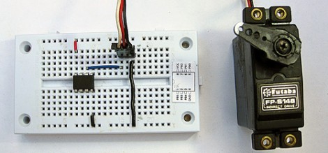
Servo8bit is a library for AVR microcontrollers that allows you to drive servo motors without the need for a 16-bit timer. Obviously, this is quite useful for smaller chips that only have 8-bit timers and it is specifically targeted at the ATtiny45 and ATtiny85 microcontrollers. The library offers 256 steps of resolution, and can drive up to five servos at one time. Servo control pulses can be generated between 512 and 2560 microseconds and if you don’t mind increasing the time between these pulses [Liya] says it would be possible to increase the 5-servo limit.

The library is quite easy to use, but in its current state it would take just a bit of work to port to another device. It’s been written for an 8 Mhz clock signal with PortB used to drive the motors. Using find-and-replace to change the PORTB keywords to use a DEFINE variable should be easy enough, but we don’t know how hard it would be to change the clock frequency.

We wonder if it’s possible to make this a slave device, perhaps implementing a 1-wire protocol?

ATtiny Hacks: ATtiny10 Game – Doing More With Less

ATtiny Hacks Theme Banner

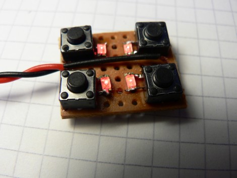
Okay, you’ve got a six-pin microcontroller with 1k of program memory, 32 bytes of SRAM, and it can’t be programmed using an In-System-Programmer. Do you think you can use it to develop a game? [Wrtlprnft] managed to build a Simon Says game based on the diminutive device that has four buttons and four LEDs. Judging from the video after the break, we’d say he nailed it!

There are so many design challenges here. First off, with only six pins total getting eight devices connected and working means doubling up on each I/O pin and using the reset pin as a doubled-up I/O. We’ve seen momentary push buttons on the same pins as LEDs before, so that’s not too hard to get working.

But if you’re using the reset pin how do you flash the thing? It doesn’t use the same ISP programming protocol that it’s bigger cousins do, so [Wrtlprnft] used an ATmega1284P to program it, hooking up to the three I/O pins and using a transistor to push 12V on the reset pin. But there’s still the matter of writing the code. It has half of the 32 registers you’d expect to find. He ended up ditching C and went straight to writing Assembly because of the diminished instruction set. It’s the first thing he’s written in Assembly, and a great way to learn the ropes.

It may not be as polished, but we do like it just as much as the Karate Chop Simon Says game which has a lot of other bells and whistles.

Continue reading “ATtiny Hacks: ATtiny10 Game – Doing More With Less”

Octocopter Will Someday Kill Someone

Above you can see Doctor Wily a Chinese hacker starting up one of the propellers on his octocopter. It seems that the man is using a collection of eight motorcycle engines, each with its own wooden propeller to create an eight-bladed helicopter. We were able to locate some video footage of his experiments, which you’ll find embedded after the break. As you can see, this is perfectly capable of flight, but we’re not quite sure if we’d call it controlled flight just yet.

The video starts off showing all kinds of hack-ity activities, like tightening the bolts on the propeller and priming the gas lines by sucking on them like a straw (mmmm….. high-octane!). Coke bottles serve as the gas tanks, and you’ll want to keep your hands inside the vehicle because there’s no cages to keep them out of the hand-started propellers. Although we don’t speak his language, we did understand the demonstration of the controls that the man gives, showing an earlier model with rings of fabric around four of the propellers meant to help direct the downward thrust as a steering mechanism. We don’t think this will be viable until there is some type of PID system that predicts the performance of each motor and makes quick adjustments to keep the craft balanced. None-the-less we were glued to the screen hoping that this turkey would fly.

Continue reading “Octocopter Will Someday Kill Someone”

USB Stick Propeller Development Board

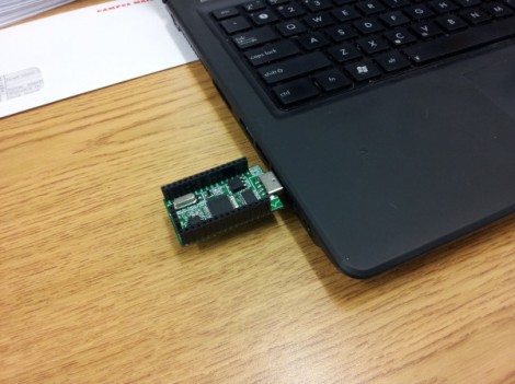
[Parker Dillmann] is nearing the end of the prototyping process for his Propeller development board. He wanted a tool that let him work on projects without the need for a bunch of equipment, while still maintaining the ability to extend the hardware when necessary. His last dev board used a large piece of protoboard to host through hole components including the Propeller chip, 3.3V and 5V regultors, an SD card reader, and female pin headers. This version migrates to a PCB from a fab house and mostly surface mount components.

He decided to use a USB-stick design having been happy with some of TI’s prototyping tools. The Parallax branded development boards use an FTDI 232RL chip for easy programming and that’s what he’s gone with as well. A P8X32A chip in the QFP package was chosen for easier soldering than the smaller QFN option. There’s also a 64kb EEPROM on board to give you plenty of room for your SPIN programs. All the pins are broken out to DIL female headers and there’s a power header on the end opposite the USB plug. [Parker] plans to do a bit of testing to make sure there’s no problems with signal routing below the 5Mhz crystal footprint. This run of prototypes came from the Seeed Studios Fusion PCB servcie–he got more than 10 boards for a total of $13… that’s almost unbelievable.