Taking The Leap Off Board: An Introduction To I2C Over Long Wires

If you’re reading these pages, odds are good that you’ve worked with I²C devices before. You might even be the proud owner of a couple dozen sensors pre-loaded on breakout boards, ready for breadboarding with their pins exposed. With vendors like Sparkfun and Adafruit popping I²C devices onto cute breakout boards, it’s tempting to finish off a project with the same hookup wires we started it with.

Image result for i2c sensor array
prototyping starts here, but we’re in danger when projects finish with this sort of wiring

It’s also easy to start thinking we could even make those wires longer — long enough to wire down my forearm, my robot chassis, or some other container for remote sensing. (Guilty!) In fact, with all the build logs publishing marvelous sensor “Christmas-trees” sprawling out of a breadboard, it’s easy to forget that I²C signals were never meant to run down any length of cable to begin with!

As I learned quickly at my first job, for industry-grade (and pretty much any other rugged) projects out there, running unprotected SPI or I²C signals down any form of lengthy cable introduces the chance for all sorts of glitches along the way.

I thought I’d take this week to break down that misconception of running I²C over cables, and then give a couple examples on “how to do it right.”

Heads-up: if you’re just diving into I²C, let our very own [Elliot] take you on a crash course. Continue reading “Taking The Leap Off Board: An Introduction To I2C Over Long Wires”

A How-To In Homebrew Design, Fab, And Assembly With Structural Framing Systems

At this point, the internet is crawling with butt-kicking homebrew 3D printers made with extruded profiles, but it’s easy to underestimate the difficulty in getting there. Sure, most vendors sell a suite of interlocking connectors, but how well do these structural framing systems actually fare when put to the task of handling a build with sub-millimeter tolerances?

I’ve been playing around with these parts for about two years. What I’ve found is that, yes, precise and accurate results are possible. Nevertheless, those results came to me after I failed and–dry, rinse, repeat–failed again! Only after I understood the limits of both the materials and assembly processes was I able to deliver square, dimensionally accurate gantries that could carry a laser beam around a half-square-meter workbed. That said, I wrote a quick guide to taming these beasts. Who are they? What flavors do they come in? How do we achieve those precision results? Dear reader, read on.

Continue reading “A How-To In Homebrew Design, Fab, And Assembly With Structural Framing Systems”

Abacus Drive Is A Speed-to-Torque Game-Changer

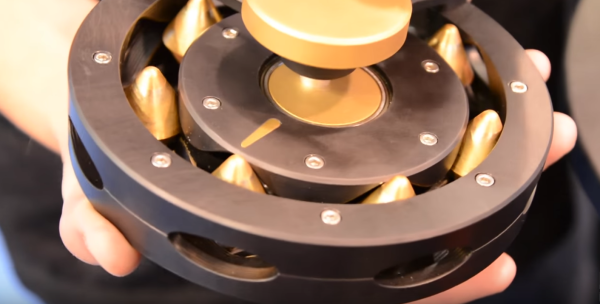
Apart from the harmonic drive, the engineering community hasn’t really come up with any clever mechanisms for speed-to-torque conversion in the last few decades. However, recently a few folks at SRI have given us one more transmission to drool over: the Abacus Drive.

The Abacus Drive takes the standard concepts of a cycloidal drive, but takes the eccentric gear tooth pattern that we’re familiar with and converts it to two grooves in which an array of rolling spacers will ride. The benefit with this design is two-fold: it’s both constructed from entirely rigid components (unlike the harmonic drive), and it has a low-backdriving torque, enabling the application to more easily detect changes in load.

Achieving an affordable low-speed, high-torque transmission has been a holy grail among roboticists, where every motor-driven manipulator joint becomes an engineering design headache where the designers fight their application’s backlash, torque, and price constraints to get a functional robot arm. This problem stems from the fact that motors just don’t perform efficiently at low-speeds, where the near-stall conditions cause them to draw vastly larger amounts of torque compared to their full-speed conditions. While the Abacus Drive isn’t hitting the market anytime soon, we’ll let this idea stew in the community and hope to see some budget variants pop up in the near future.

Continue reading “Abacus Drive Is A Speed-to-Torque Game-Changer”

Drop-in Laser Cutter Alignment Beam Works Like A Charm

Every laser cutter enthusiast eventually pops the question: how on earth do I align an invisible beam that’s more-than-happy to zap my eyeballs, not to mention torch everything else in its path? We hate to admit it, but laser cutter beam alignment is no easy task. To greatly assist in this endeavor, though, some folks tend to mix a red diode laser into the path of the beam. Others temporarily fixture that diode laser directly in the beam path and then remove it once aligned.

One deviant has taken diode laser mixing to the next level! [Travis Reese] has added a servo-driven diode laser that dynamically drops into the path of the laser tube when the lid pops up, and then tilts comfortably out of the laser path when the lid closes again.
Continue reading “Drop-in Laser Cutter Alignment Beam Works Like A Charm”

90+ Videos Take You From Laser Chump To Laser Champ

Few of us document the progression of our side projects. For those who do, those docs have the chance at becoming a tome of insight, a spaceman’s “mission log” found on a faraway planet that can tell us how to tame an otherwise cruel and hostile world. With the arrival of the RDWorks Learning Lab Series, Chinese laser cutters have finally received the treatment of a thorough in-depth guide to bringing them into professional working order.

In two series, totalling just over 90 videos (and counting!) retired sheet-metal machinist [Russ] takes us on a grand tour of retrofitting, characterizing, and getting the most out of your recent Chinese laser cutter purchase.

Curious about laser physics? Look no further than part 2. Wonder how lens size affects power output? Have a go at part 39. Need a supplemental video for beam alignment? Check out part 31. For every undocumented quirk about these machines, [Russ] approaches each problem with the analytic discipline of a data-driven scientist, measuring and characterizing each quirk with his suite of tools and then engineering a solution to that quirk. In some cases, these are just minor screw adjustments. In other cases, [Russ] shows us his mechanical wizardry with a custom hardware solution (also usually laser cut). [Russ] also brings us the technical insight of a seasoned machinist, implementing classic machinist solutions like a pin table to produce parts that have a clean edge that doesn’t suffer from scatter laser marks from cutting parts on a conventional honeycomb bed.

Solid build logs are gems that are hard to come by, and [Russ’s] Chinese laser cutter introduction shines out as a reference that will stand the test of time. Don’t have the space for a laser cutter? For the micromachinists, have a look at The Guerrilla Guide to CNC Machining, Mold Making, and Resin Casting.

Continue reading “90+ Videos Take You From Laser Chump To Laser Champ”

Taig Mill Anointed With Ball Screws (at Last!)

Yup, we can hear a crowd full of “not-a-hack” loading their cannons as we speak, but this machine has a special place in the community. For years, the Taig milling machine has remained the go-to micro mill for the light-duty home machine shop. These machines tend to be adorned and hacked to higher standards, possibly because the community that owns these tools tends to enjoy machining for machining’s sake–or possibly because every single component of the mill is available as a replacement part online. For many, this machine has been a starting point to making chips at home. (In fact, Other Machine Co’s CTO, Mike Estee, began his adventure into machining with a Taig.)

For years, Taig has sold their machines with a leadscrew and a brass nut that could be tensioned to cut down the backlash. Backlash still remains an issue for the pickiest machinists, though; so, at long last, Taig has released a backlash-free ball-screw variant in two incarnations: an all-in-one machine pre-fitted with ballscrews and an upgrade kit for customers that already decorated their garage with the lead-screw model.

In the clip below [John] takes us on a tour of the challenges involved in cramming 3, 12-mm ballscrews into the original topology. As we’d expect, a few glorious chunks of metal have been carved away to make space for the slightly-larger ballnut. Despite the cuts, the build is tidy enough to fool us all into thinking that ballscrews landed in the original design from the start.

Confused why ballscrews are such a giant leap from leadscrews? Lend your eyes and ears a few moment to take in [Al]’s overview on the subject.

Continue reading “Taig Mill Anointed With Ball Screws (at Last!)”

Two-Stage Tentacle Mechanisms Part III: Putting It All Together

Welcome back to the final chapter in our journey exploring two-stage tentacle mechanisms. This is where we arm you with the tools and techniques to get one of these cretins alive-and-kicking in your livingroom. In this last installment, I’ll guide us through the steps of building our very own tentacle and controller identical to one we’ve been discussing in the last few weeks. As promised, this post comes with a few bonuses:

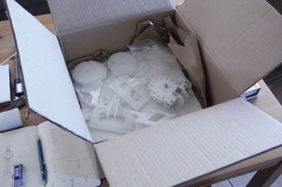
29323707092_28d8bd1eb8_z
Nothing like a fresh batch o’ parts.

Design Files

  1. The Almighty Bill-o’-Materials
  2. Vector Drawings for laser cutting
    1. DXF files pre-offset (0.003″)
    2. DXF files original
  3. STL Models for 3D Printing
  4. Original Tentacle CAD Model Files
  5. Original Controller CAD Model Files

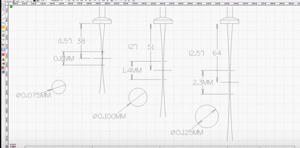
Depending on your situation, some design files may be more important than others. If you just want to get parts made, odds are good that you can simply cut the pre-offset DXFs from the right plate thicknesses and get rolling. Of course, if you need to tune the files for a laser with a slightly different beam diameter, I’ve included the original DXFs for good measure. For the heavy-hitters, I’ve also included the original files if there’s something about this design that just deserves a tweak or two. Have at it! (And, of course, let us know how you improve it!)

Ok, now that we’ve got the parts on-hand in a pile of pieces,let’s walk through the last-mile tweaks to making this puppet work: assembly and tuning. At this point, we’ve got a collection of parts, some laser-cut, some off the shelf. Now it’s time to string them together.

Continue reading “Two-Stage Tentacle Mechanisms Part III: Putting It All Together”