Perler Printer Pushes Pixel-Art Like No Sprite Artist Could

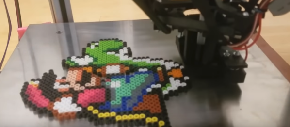
There’s something oddly soothing about the practice of laying down Perler Beads on a casual weekend to make your favorite classic Nintendo characters. But seriously, why use our grubby hands like a caveman when we could leverage a machine to do the heavy-lifting for us? That’s exactly what [knezuld11] did! They’ve built a 64-color Bead Sprite Printer including an automatic cooking feature for fusing the result. (Video, embedded below.)

From the top, up to 64 unique bead colors are stashed into cartridges at the top. A bulk agitator does the work of passing these beads into tubes for the lower-stage bead selector. At this level, beads colors are serialized into a single tube that feeds into the output “nozzle.” The entire process of directing the bead pattern is driven by a Python script that takes images as input and approximates their colors to the available bead palette. When the bead “printing” is done, the machine ramps up its heated bed and cooks the bottoms of the beads, fusing them together in a way that [knezuld11] says works actually better than the typical ironing method.

We simply love how feature-complete this system is. While [knezuld11] mentioned that the Bead Sprite Printer was an attempt at beating a world record, we imagine that there are dozens of other ways this machine could lead to some whimsical engagements. Quite frankly, we’d love to see this machine at an Artist Alley making on-demand art.

If you managed to spill all your beads from sheer excitement watching this video, fret not! This automatic bead sorter from our past is just the thing to help you out.

Continue reading “Perler Printer Pushes Pixel-Art Like No Sprite Artist Could”

Literal Stretch-Sensing Glove Reconstructs Your Hand Poses

Our hands are rich forms of gestural expression, but capturing these expressions without hindering the hand itself is no easy task–even in today’s world of virtual reality hardware. Fret not, though, as researchers at the Interactive Geometry Lab have recently developed a glove that’s both comfortable and straightforward to fabricate while capturing not simply gestures but entire hand poses.

Like many hand-recognition gloves, this “stretch-sensing soft glove” mounts the sensors directly into the glove such that movements can be captured while hands are out of plain sight. However, unlike other gloves, sensors are custom-made from two stretchable conductive layers sandwiched between a plain layer of silicone. The result is a grid of 44 capacitive stretch sensors. The team feeds this datastream into a neural network for gesture processing, and the result is a system capable of reconstructing hand poses at 60Hz refresh rates.

In their paper [PDF], the research team details a process of making the glove with a conventional CO2 laser cutter. They first cast a conductive silicone layer onto a conventional sheet of silicone. Then, with two samples, they selectively etch away the conductive layer with the unique capacitive grid images. Finally, they sandwich these layers together with an additional insulating and glue it into a hand-shaped textile pattern. The resulting process is a classy use of the laser cutter for the design of flexible capacitive circuits without any further specialized hardware processes.

While we’re no stranger to retrofitting gloves with sensors or etching unconventional materials, the fidelity of this research project is in a class of its own. We can’t wait to see folks extend this technique into other wearable stretch sensors. For a deeper dive into the glove’s capabilities, have a look at the video after the break.

Continue reading “Literal Stretch-Sensing Glove Reconstructs Your Hand Poses”

Books You Should Read: Exact Constraint: Machine Design Using Kinematic Principles

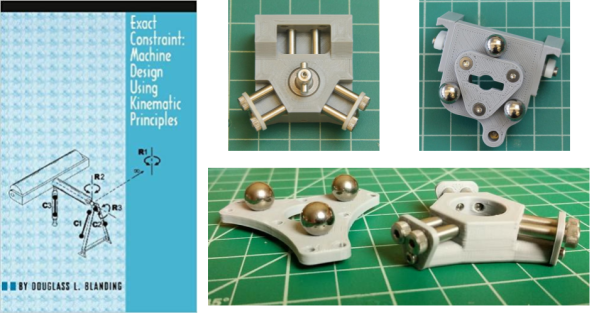
Surely, if you’re reading this website you’ve teased the thought of building your own 3D printer. I certainly did. But from my years of repeated rebuilds of my homebrew laser cutter, I learned one thing: machine design is hard, and parts cost money. Rather than jump the gun and start iterating on a few machine builds like I’ve done before, I thought I’d try to tease out the founding principles of what makes a rock-solid machine. Along the way, I discovered this book: Exact Constraint: Machine Design Using Kinematic Principles by Douglass L. Blanding.

This book is a casual but thorough introduction to the design of machines using the method of exact constraint. This methodology invites us to carefully assess how parts connect and move relative to each other. Rather than exclusively relying on precision parts, like linear guides or bearings, to limit a machine’s degrees of freedom, this book shows us a means of restricting degrees of freedom by looking at the basic kinematic connections between parts. By doing so, we can save ourselves cost by using precision rails and bearings only in the places where absolutely necessary.

While this promise might seem abstract, consider the movements made by a 3D printer. Many styles of this machine rely on motor-driven movement along three orthogonal axes: X, Y, and Z. We usually restrict individual motor movement to a single axis by constraining it using a precision part, like a linear rod or rail. However, the details of how we physically constrain the motor’s movements using these parts is a non-trivial task. Overconstrain the axis, and it will either bind or wiggle. Underconstrain it, and it may translate or twist in unwanted directions. Properly constraining a machine’s degrees of freedom is a fundamental aspect of building a solid machine. This is the core subject of the book: how to join these precision parts together in a way that leads to precision movement only in the directions that we want them.
Part of what makes this book so fantastic is that it makes no heavy expectations about prior knowledge to pick up the basics, although be prepared to draw some diagrams. Concepts are unfolded in a generous step-by-step fashion with well-diagrammed examples. As you progress, the training wheels come loose, and examples become less-heavily decorated with annotations. In this sense, the book is extremely coherent as subsequent chapters build off ideas from the previous. While this may sound daunting, don’t fret! The entire book is only about 140 pages in length.

Continue reading “Books You Should Read: Exact Constraint: Machine Design Using Kinematic Principles”

Bearing-reinforced Stepper Tackles Hefty Axial Loads

These days, it’s common among us hackers to load a stepper motor with forces in-line with their shaft–especially when we couple them to leadscrews or worm gears. Unfortunately, steppers aren’t really intended for this sort of loading, and doing so with high forces can destroy the motor. Fear not, though. If you find yourself in this situation, [Voind Robot] has the solution for you with a dead-simple-yet-dead-effective upgrade to get your steppers tackling axial loads without issue.

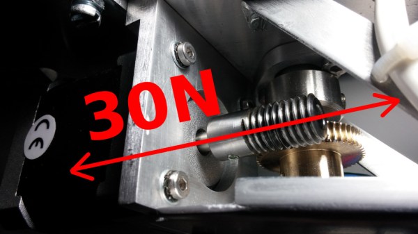
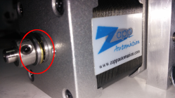
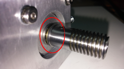
In [Voind Robot’s] case, they started with a worm-gear-drive on a robot arm. In their circumstances, moving the arm could put tremendous axial loads onto the stepper shaft through the worm–as much as 30 Newtons. Such loads could easily destroy the internal stepper motor bearings in a short time, so they opted for some double-sided reinforcement. To alleviate the problem, the introduced two thrust bearings, one on either side of the shaft. These thrust bearings do the work of redirecting the force off the shaft and directly onto the motor casing, a much more rigid place to apply such loads.

This trick is dead simple, and it’s actually over five years old. Nevertheless, it’s still incredibly relevant today for any 3D printer builder who’s considering coupling a leadscrew to a stepper motor for their Z-axis. There, a single thrust bearing could take out any axial play and lead to an overall rigid build. We love simple machine-design nuggets of wisdom like these. If you’re looking for more printer-design tricks, look no further than [Moritz’s] Workhorse Printer article.

E3D’s Love Letter To Toolchanging 3D Printers

It’s been just over a year since E3D whetted our appetites for toolchanging printers. Now, with the impending release of their first toolchanging system, they’ve taken the best parts of their design and released them into the wild as open source. Head on over to Github for a complete solution to exchanging, locating, and parking tools on a 3D printer.

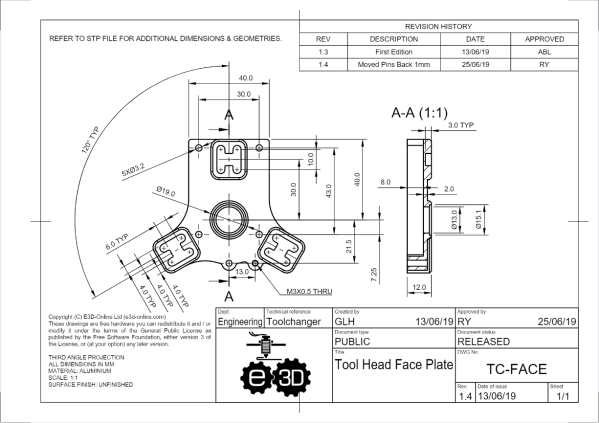
For anyone interested in fabricating the design, the files are in a format that you can almost re-zip and email to a manufacturer for quotes. As is, the repository offers STP-style CAD files, a complete set of dimensioned drawings, exploded views, and even a bill of materials. Taken as a whole, the system elegantly solves the classic problems that we’d encounter in toolchanging. Locking tools is done with a spring-based T-bar that swivels onto an wedge-shaped groove on the back of each tool plate. Locating tools is done so with a 3-groove kinematic coupling fabriacted from dowel pins. With these problems solved and presented so cleanly, these files become a path by which we can establish a common means for exchanging tools on 3D printer systems.

It’s worth asking: why develop an exceptional design and then release it for free? I’ll speculate that E3D has done an excellent job over the years establishing a well-recognized standard set of stock parts. Nearly every 3D printer builder is bound to have at least one spare V6 hotend sitting idle in a disassembled pool of former-3D-printers. With tool-changing positioned to become another step forward in the space of possibilities with 3D printing, setting the standard for tools early encourages the community to continue developing applications that lean on E3D’s ecosystem of parts.

In the last 30 years, 3D printing has transformed away from a patent-trolling duopoly to a community-friendly group of contributors that lean on each other’s shoulders with shared findings. It’s a kind gesture to the open-source community of machine builders to receive such a feature-complete mechanism. With that said, let’s start rolling the toolchanger hacks.

LED Music Visualizer Bespeckles Your Bedroom

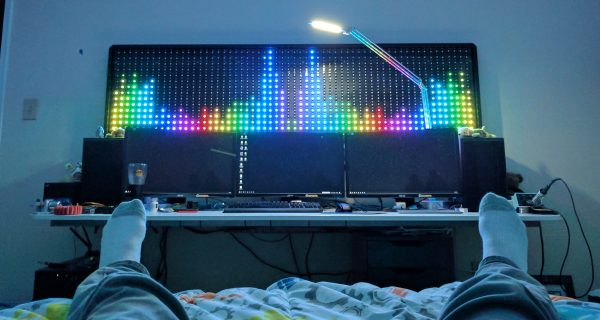
When it comes to wall-mounted ornamentation, get ready to throw out your throw-rugs and swap them for something that will pop so vividly, you’ll want to get your eyes checked. To get our eyes warmed up and popping, [James Best] has concocted a gargantuan 900-RGB-LED music visualizer to ensure that our bedrooms are bright and blinky on demand.

Like any other graduate from that small liberal-arts school in southern California, [James] started prototyping with some good old-fashioned blue tape. Once he had had his grid-spacing established, he set to work on 2-meter-by-0.5-meter wall mounted display from some plywood and lumber. Following some minor adhesive mishaps, James had his grid tacked down with Gaffers tape, and ready for visuals.

Under the hood, a Teensy is leveraging its DMA capabilities to conduct out a bitstream to 900 LEDs. By using the DMA feature and opting for a Teensy over the go-to Arduino, [James] is  using the spare CPU cycles to cook out some Fourier-Transformed music samples and display their frequency content.

We’ve covered folks proving the concept of driving oodles of WS2812B LEDs over DMA; it’s great seeing these ideas mature into a fully-featured project that lands on the walll. For more on chatting with WS2812B LEDs over DMA, have a look back into our archive.

Continue reading “LED Music Visualizer Bespeckles Your Bedroom”

Microscope-Inspired Toolchanger Spins Multicolor 3D Prints

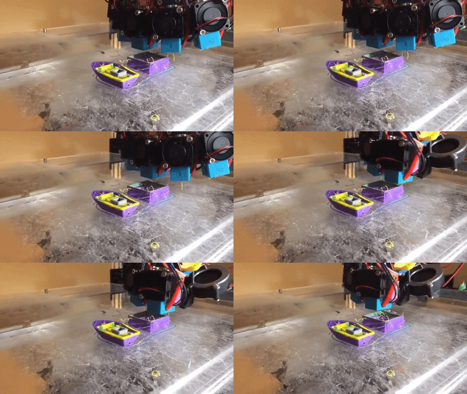
The 3D printing community is simply stirring with excitement over toolchanging printers, but these machines are still the exception rather than the norm. Here’s an exceptional exception: [Paul Paukstelis] built a five-color printer with a novel head-changing solution.

[Paul’s] 3D printer is a hat-tip to anyone who’s spent time in the wetlab. For starters, the printer is born from the remains of a former liquid handling system, a mighty surplus score. When it comes to headchanging, [Paul] combined some honest inspiration from E3D’s toolchanging videos with some design features borrowed from the microscope in his lab. The result is that the printer’s five-tool head-changer mechanically behaves very similarly to the nose piece in a compound light microscope.

Because the printer evolved from old lab equipment, [Paul] dubs his printer into a lineage that he calls the “Reclaimed Rapid-Prototyper,” or the RecRap. Best of all, he’s kindly posted up the CAD files on the Thingiverse such that you too can take a deep look into this head-changing solution.

We love seeing these tools get a second life, and we think there’s plenty of potential for new offspring in this lineage of discarded lab equipment.

Continue reading “Microscope-Inspired Toolchanger Spins Multicolor 3D Prints”