The K9 Curfew Door

[Kenbob] is an awesome pet owner. He has two small dogs that have free access to the backyard through a doggy door. It’s great during the day, but they have to close it at night to stop the dogs from bothering the neighbors. So he decided to make an automatic curfew based doggy door!

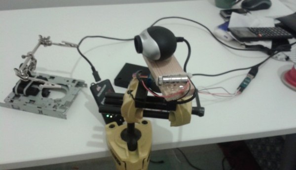
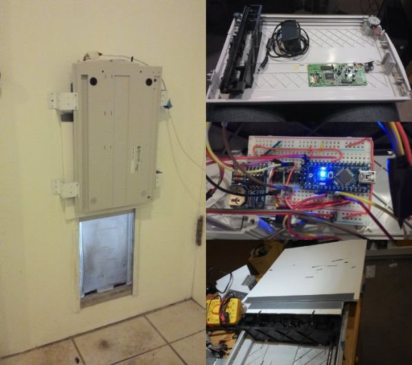
Before setting out on his project, he determined some design goals that had to be met. Namely, he couldn’t have it lock the dogs outside by accident! The hack makes use of an old large format flat-bed scanner that had stopped working a while ago. As it so happened, this scanner had just enough carriage travel to be able to actuate a cover for the doggy door. After reinforcing the sliding cover, he hooked it up to an Arduino Nano, a RTC and a H-Bridge motor driver in order to control it.

In order to add scheduling ability and to program the door remotely, he has also hooked it into his existing x10 control infrastructure in his house — not too shabby! It also features a manual 3-position switch to lock it open, closed, or to leave it on automatic. The question is, can a raccoon get in?

He’s been testing it for a few weeks and it works quite well, although he admits it is not the most rugged solution — lucky for him, his dogs aren’t the type to run headfirst into things. Stick around after the break to see it in action.

Continue reading “The K9 Curfew Door”

2D Room Mapping With A Laser And A Webcam

[Shane Ormonde] recently learned how to measure distance using just a webcam, a laser, and everyone’s favorite math — trigonometry. Since then he’s thrown the device onto a stepper motor, and now has a clever 2D room mapping machine.

He learned how to create the webcam laser range finder from [Todd Danko], a project we featured 7 years ago! It’s a pretty simple concept. The camera and laser are placed parallel to each other at a known distance, axis-to-axis. On the computer, a python script (using the OpenCV library) searches the image for the brightest point (the laser). The closer the brightest point is to the center of the image, the farther the object. Counting pixels from the center of the image to the laser point allows you to calculate an angle, which can then be used to calculate the distance to the object — of course, this needs to be calibrated to be at all accurate. [Shane] does a great job explaining all of this in one of his past posts, building the webcam laser rangefinder.

From there it was just a matter of slapping the rangefinder onto a stepper motor, driving it with a small PIC, and running the calculations on the fly! His results are fairly impressive.

Continue reading “2D Room Mapping With A Laser And A Webcam”

RIVERWATCH: An Autonomous Surface-Aerial Marsupial Robot Team

cata

Every once in a while we get a tip for a project that really, really, really blows our minds. This is one of them.

It looks like a basic catamaran with a few extra bells and whistles — except it is so much more than that. You’re looking at a fully Autonomous Surface Vehicle, complete with a piggybacking 6-rotor UAV. It’s decked out in cameras, sonar sensors, laser rangefinders, high accuracy GPS-RTK tracking, an IMU, oh, and did we mention the autonomous 6-rotor UAV capable of taking off and landing on it?

It all started out as a simple experiment within ECHORD (the European Clearing House for Open Robotics Development), and since then it has become a fully funded project at UNINOVA, a Centre of Technology and Systems in Portugal.

The purpose of the mind-blowing robot team is to collect data of river environments — think of it as Google Maps 2.0 — which is almost an understatement for what it is capable of.

You seriously have to watch the video after the break.

Continue reading “RIVERWATCH: An Autonomous Surface-Aerial Marsupial Robot Team”

S.A.M. The Safety Attention Monitor

Capture

Last term’s project at Chico State University hopes to reduce driver distraction by alerting you when it notices you aren’t paying attention (to the road!).

The team designed SAM using OpenCV to track your face in order to recognize when you aren’t watching the road. It alerts you through a variety of audible beeps and LED lights, and is programmed to only alert you after set time values — i.e. it’s not going to go off when you’re checking your blind spot, unless you’ve been checking it for over a certain length of time. It also has a silence button you can press for situations like looking around while you are parked.

The proof of concept device was built using a Raspberry Pi, the PiCam, and a breadboard to accommodate some manual controls, the buzzer, and LEDs. It also continuously records video of you on a 30 second loop, and in the event of an accident, it saves all the video — perhaps proving it was your fault. Can you imagine if all cars had this installed? On the plus side you wouldn’t have to argue with insurance companies — but if it really was your fault, well then you’re straight out of luck.

Iowa Forensics Opts For A CSI Style Hack To Save Their Budget

Stungun

There’s a very effective way of lifting dusty fingerprints from the field, or in a lab. It’s called an Electrostatic Dust Print Lifter — but as you can imagine, it is rather expensive from a forensic supply store. [Bradley VanZee] — from the Iowa Division for International Association for Identification — realized how simple a tool it was, and made his own for just over $50.

But first, how does it work? Electrostatic print lifting is a non-destructive process where you develop an electrostatic field on a sheet of “lifting film” which attracts the dust particles to stick to the film. It’s capable of recovering impressions from both porous and non-porous surfaces — even ones not visible to the naked eye.

Commercial versions of the tool cost upwards of $600-$800 + lift film. The first hack they realized is that instead of using proprietary lift film, it is just as effective to use car window tint instead! The second hack is even more clever — using a 80,000V tazor, some electrical leads, and some tinfoil you can create your own version of the tool. The aluminum foil acts as a ground, and the object you are inspecting is sandwiched between it and the lifting film. Holding the tazor with one electrode to the foil, you can trace the film using the other electrode at a distance, which induces an electrostatic charge in the film, attracting and capturing the dusty fingerprints. Allow the static to discharge, and store the film in a safe place to be digitized later!

Now obviously this is only really effective for flat objects, but it’s still a brilliant hack — especially to save your budget!

[Thanks John!]

The Robot Operating System (ROS) 101

Ever heard about the Robot Operating System? It’s a BSD-licensed open-source system for controlling robots, from a variety of hardware. Over the years we’ve shared quite a few projects that run ROS, but nothing on how to actually use ROS. Lucky for us, a robotics company called Clearpath Robotics — who use ROS for everything — have decided to graciously share some tips and tricks on how to get started with ROS 101: An Introduction to the Robot Operating System.

The beauty of the ROS system is that it is made up of a series of independent nodes which communicate with each other using a publish/subscribe messaging model. This means the hardware doesn’t matter. You can use different computers, even different architectures. The example [Ilia Baranov] gives is using an Arduino to publish the messages, a laptop subscribed to them, and even an Android phone used to drive the motors — talk about flexibility!

It appears they will be doing a whole series of these 101 posts, so check it out — they’ve already released numéro 2, ROS 101: A Practical Example. It even includes a ready to go Ubuntu disc image with ROS pre-installed to mess around with on VMWare Player!

And to get you inspired for using ROS, check out this Android controlled robot using it! Or how about a ridiculous wheel-chair-turned-creepy-face-tracking-robot?

Tesla Coil Auto-Winder

tesla winder

Tesla coils are awesome. But if you’ve ever built one, you know how tedious winding the secondary coil is. So [Krux] decided to build a machine to do it for him.

He’s currently working on his first Tesla coil — code-named Project Icarus — he doesn’t have all the logistics ironed out quite yet, but he’s been slowly collecting the components. What he does know is that he wants to use a 4.5″ secondary coil, using 22AWG magnet wire, meaning that’s a lot of turns! Since he’s also a member of a local hackerspace, he decided to make it a modular machine that can wind different sized coils for different sized projects.

Essentially, he’s built his own CNC lathe to accomplish this, well, missing one axis. There’s the main rotary axis, and a wire-guide that moves along it ensuring the coils are wrapped tightly without gaps. It’s an impressive build and you can tell he’s put a lot of thought into the design — He’s even got a semi-flexible 3D printed motor coupler on the wire-guide axis, to help mitigate quick acceleration! The main rotary axis is also driven by a 3D printed herringbone style gear — similar to the style used on Printrbot extruders. The rest of the build is made of plywood and pegboard — allowing for even larger coils to be wound by shuffling around the components. He’s even got a full featured command console with manual/automatic controls and an LCD giving feedback on the coil being wound!

Stick around after the break to see [Krux] explain the fascinating build, and to see a fun time-lapse of an 814-turn Tesla coil winding!

Continue reading “Tesla Coil Auto-Winder”