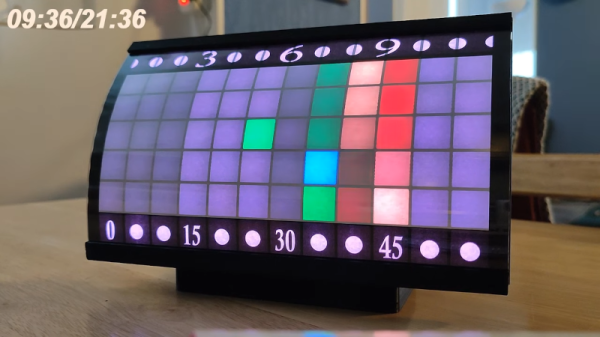
While we’re told that space-time curves, we aren’t sure that was what [andrei.erdei] was going for when he built a great-looking curved LED clock. The LEDs are courtesy of a strip of 84 WS2812 smart LEDs, the curve comes from a 3D printed part, and a Wemos D1 mini provides the brains.
Like all of our favorite clocks, this one has a unique way of displaying the time. If you find the description in the post hard to understand, the video below makes it a bit easier to wrap your head around. Note the time appears in the top left corner of the video in several cases — so you can check to see if you’re reading it correctly.
The secret sauce, of course, is the curved plastic grid that holds the LEDs. Because of the unusual shape, supports are a must and there are notes in the post about the settings used to get the best results. With 84 LEDs, the software has to be careful not to turn them to full brightness at one time, or else the clock would need a 6 amp power supply. Instead, the software limits the brightness to a little less than half of the maximum. No LED is ever white, and not all LEDs are on at once. The clock works easily, according to [andrei], with a 2 A supply. The clock has a WiFi connection where you can set things up easily.
Overall, a nice-looking project that would look at home on a science fiction movie set. We’ve seen color clocks before. If you want to economize on LEDs, we’ve seen a clock with only five!
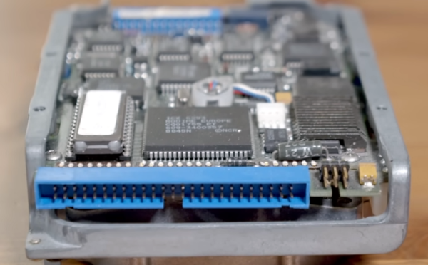
Early home PCs usually had a floppy disk and a simple hard drive controller. Later, IDE hard drives became the defacto standard. Of course, these days, you are more likely to find some version of SATA and — lately — NVME connectors. But a standard predating all of this was very common in high-end systems: SCSI. [RetroBytes] recently did a video on the bus which he calls the “USB of the 80s.”
Historically, Shugart — a maker of disks — was tired of producing custom drive electronics for each device they made. Instead, they made disks with a standard interface and then produced a single interface board for each computer they wanted to support. The interface was very generic, and they were able to get it standardized with ANSI — an early example of the benefit of opening up a standard.
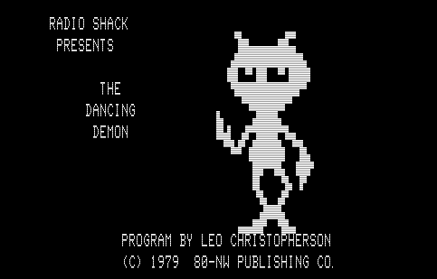
Even if you didn’t own a TRS-80, the widespread footprint of Radio Shack in malls meant that if you are old enough, it is a good bet you have seen one and maybe even played with one. The games were crude, but state-of-the-art for 1982. If you wanted business software, that was there too, just don’t expect much on any of the personal computers of the day. My old TRS-80 Model III doesn’t boot anymore and is waiting for me to find time to pull it apart. But it turns out you can run all those old programs with almost no effort. If you’ve experimented with emulators before, you know there are two major problems. First, you need to install the sometimes-fidgety emulator. Second, you need to find the software you want to run and probably convert it into some format the emulator will read. The website named The Big List of TRS-80 Software solves both problems.
You are probably thinking this doesn’t solve any problem because it is just a list of links to software. That’s a reasonable thing to think, but we think the website really needs a new name. There are 15,873 pieces of software on the site, although some of them are duplicates or multiple versions of a single program. You can download them in a format that is useful for some emulators or, in some cases, the original files. But here’s the kicker. You can also click to launch a virtual TRS-80 in your browser and start the program.
Sounds great, right? Well, for the most part, it is. However, some of the programs are finicky and don’t run well in the browser. There’s also the problem of finding the documentation, but you can’t have everything. If you want a quick run of a very common game from back in the day, try Flying Saucers. Continue reading “Emulating All The TRS-80 Software”→
Before video games, there were pinball machines. Not that they don’t exist today, but a modern pinball machine will likely have microprocessors and other fancy things that traditional pinball machine designers could never dream of. [Eli] had one of these mechanical machines from 1974 as a kid and, later, encountered a more modern machine with a rudimentary microprocessor and other integrated circuits onboard. One thing this enabled is the ability to remember high scores. But you have to physically look at the machine, and you can only see the top four scores. [Eli] decided to adapt the machine to upload high score data to the Internet, and it is a fun project.
[Eli]’s design goals were to make it automatic and robust. That is, if the network is down or the machine loses power, you shouldn’t lose high score data. In addition, he didn’t want to change the appearance or damage the 40-year-old machine. You can see a video of how it all turned out below.
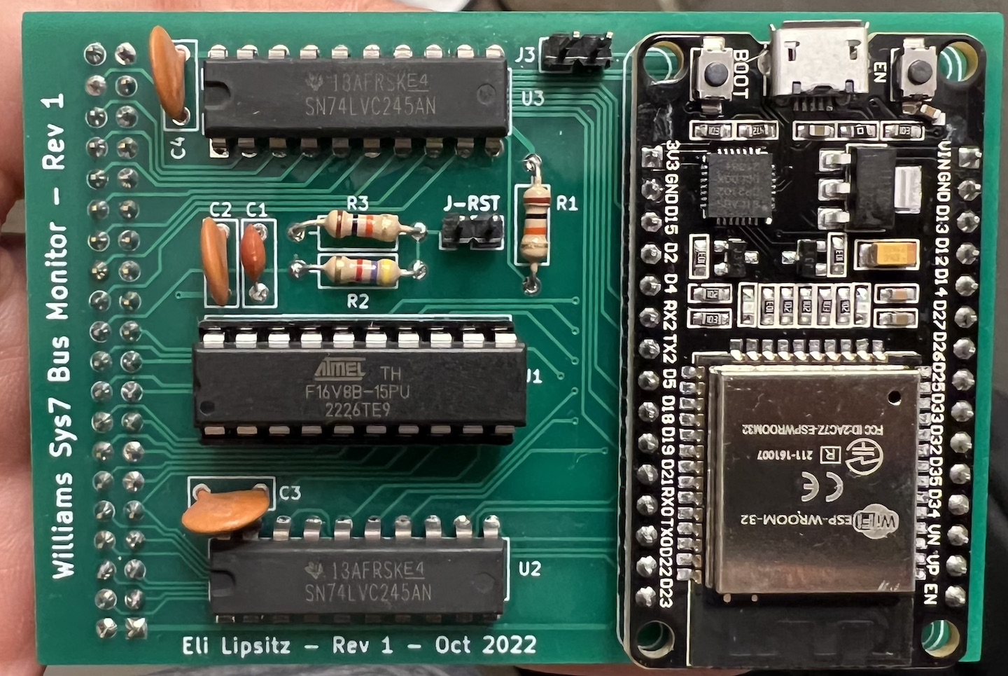
The Laser Cue machine is one of many built around the “Williams System 7” platform. A 6808 CPU, along with some I/O chips to manage all the lights, sensors, and bells. The game has only 1K of RAM, 12K or ROM, and 128 bytes (no prefix, just bytes) of RAM with battery backup. There was even a common “operating system” called Flipper ROM, and that’s actually documented over on GitHub.
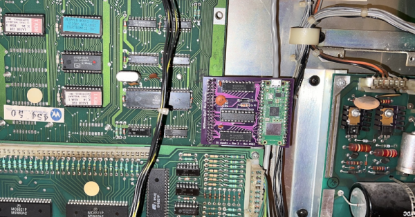
The ESP32 version of the WiFi interface board
Since the memory for the machine is all in external chips, it was a reasonable idea to replace the CPU with a board that monitored signals on the board. The CPU would plug into this new board, and then a newer microcontroller with an Internet connection could eavesdrop on bus traffic. However, removing the old CPU and jamming pins into the ancient socket was worrisome, so instead, [Eli] elected to tap into a test connector that was already on the board but not plugged into anything.
An ESP32 is more than capable of the speeds, although connecting to 5 V logic was a bit of a problem. The CPU has 5 V tolerant pins, but some of the 25 available pins on the development board either set items on boot or may briefly be outputs and were thus unusable. To reduce the necessary pins, [Eli] decided to do some of the decoding in separate logic. Instead of using TTL chips, he elected to use a programmable logic array.
After that, it seemed it would be straightforward, but there was something preventing the ESP32 from reading each bus cycle. [Eli] never got to the bottom of it but instead switched to the Raspberry Pi Pico W. Using the chip’s special I/O processors made the job easy, and it worked perfectly. The rest of the project was just fit and finish. Be sure to read to the end to find out the lessons learned which might help you on your next similar project.
A modern DIY machine might even have an FPGA inside. Don’t have room for a big full-sized pinball machine? No problem.
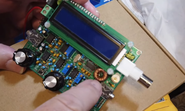
HF radios often use toroidal transformers and winding them is a rite of passage for many RF hackers. [David Casler, KE0OG] received a question about how they work and answered it in a recent video that you can see below.
Understanding how a conventional transformer works is reasonably simple, but toroids often seem mysterious because the thing that makes them beneficial is also what makes them confusing. The magnetic field for such a transformer is almost totally inside the “doughnut,” which means there is little interaction with the rest of the circuit, and the transformer can be very efficient.
The toroid itself is made of special material. They are usually formed from powdered iron oxide mixed with other metals such as cobalt, copper, nickel, manganese, and zinc bound with some sort of non-conducting binder like an epoxy. Ferrite cores have relatively low permeability, low saturation flux density, and low Curie temperature. The powder also reduces the generation of eddy currents, a source of loss in transformers. Their biggest advantage is their high electrical resistivity, which helps reduce the generation of eddy currents.
If you haven’t worked through how these common little transformers work, [David]’s talk should help you get a grip on them. These aren’t just for RF. You sometimes see them in power supplies that need to be efficient, too. If you are too lazy to wind your own, there’s always help.
All of the machine language stuff coming out lately doesn’t affect you if you are developing with embedded microcontrollers, right? Perhaps not. Microsoft Research India wants you to use their EdgeML tool to do machine learning tasks such as gesture recognition in tiny devices like an Arduino Uno. According to the developers, you might need as little as 2 KB of RAM. There’s no network connection required and the work is using Tensorflow underneath, so it is compatible with much of what you’ll find for bigger computers.
If you add processing power, you can get more capability. For example, one of the demonstrations is a wake-word recognizer on a Raspberry Pi Zero (although the page for that demo seems to be missing at the moment; try the GesturePod, instead).
The system generally uses Python, but there are efficient C++ implementations for selected algorithms. The code lives on GitHub. There are also a number of research papers about each tool that you can find on the GitHub page. There’s also a recent paper on MinUn, an attempt to make things even more efficient for ARM microcontrollers. In particular, MinUn can store approximate numbers to save space, allows for variable precision of tensors, and tries to reduce memory fragmentation, an important feature for CPUs that don’t have memory management units.
If you haven’t studied TensorFlow yet, start here. Why use something like this with a microcontroller? How about smarter robots?
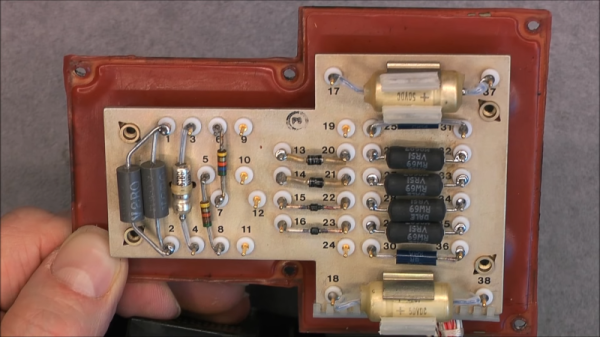
It isn’t clear to us how [mrsylvain59] came into possession of a late-model piece of military gear from the German airforce, but we enjoyed watching the teardown below anyway. According to the documentation, the thing has a huge price tag, although we all know that the military usually pays top dollar for various reasons, so we are guessing the cost of the parts is quite a bit less than the price tag.
We don’t think [mrsylvain59] was sure what the amplifier (verstärker is German for amplifier) does. However, we recognized it as an avionics box from a UH-1 helicopter. We aren’t sure of its exact function, but it is classified under “Automatic Pilot Mechanisms and Airborne Gyro Components.”