WS2811 SPI Driver Using One Transistor And Passives

ws2811-spi-driver

We love the WS28xx projects because even if we never plan to use them, the signal timing is like the most addictive puzzle game ever. For instance, check out this WS2811A driver which uses hardware SPI to generate the signals.

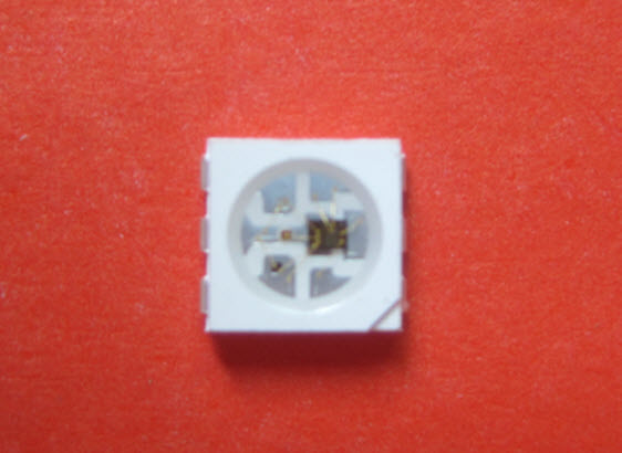
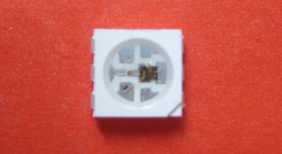
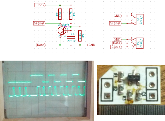
The WS28xx offerings place a microcontroller inside an RGB LED, allowing them to be individually addressed in very long chains or large matrices (still a chain but different layout). But the timing scheme used to address them doesn’t play well with traditionally available microcontroller peripherals. [Brett] had been intrigued by some of the attempts to bend hardware SPI to the will of the WS2811 — notably [Cunning_Fellow’s] work featured in this post. He took it a great step forward by simplifying the driver to just one transistor, three resistors, and a capacitor.

Click through the link above for his step-by-step description of how the circuit works (it’s not worth re-explaining here as he does a very concise job himself). The oscilloscope above shows the SPI signal on top and the resulting timing signal below. You will notice the edges aren’t very clean, which requires the first pixel to be very close to the driver or risk further degradation. But, since the WS28xx drivers feature a repeater which cleans up signals like this, it’s smooth sailing after the first pixel.


Three Conceptual Approaches To Driving A WS2811 LED Pixel

driving-a-ws2811

[Cunning_Fellow] published a post with three proof-of-concept approaches to driving a WS2811 LED pixel. We looked at a project early in December that used an AVR microcontroller to drive the RGB package. [Cunning_Fellow] saw this, and even though he doesn’t have any of these parts on hand he still spent the time hammering out ways to overcome the timing issues involved with address the device. His motto is “put up or shut up” when it comes to criticizing projects featured on Hackaday. We love seeing someone pick up an idea and run with it.

The approach in all three cases aims to conserve clock cycles when timing the communications. This leaves the developer as many cycles as possible to perform other tasks than simply telling the lights what to do. One approach is an assembly routine that is just a shade slower but groups all 14 free cycles into one block. The next looks at using external 7400 series hardware. The final technique is good old-fashioned bit banging.

[Photo Credit]

Driving A WS2811 RGB LED Pixel

[Alan] has been working on driving this WS2811 LED module with an AVR microcontroller. It may look like a standard six-pin RGB LED but it actually contains both an LED module and a microcontroller to drive it. This makes it a very intriguing part. It’s not entirely simple to send commands to the module as the timing must be very precise. But once the communication has happened, the LED will remain the same color and intensity until you tell it otherwise. You can buy them attached to flexible strips, which can be cut down to as few as one module per segment. The one thing we haven’t figure out from our short look at the hardware is how each pixel is addressed. We think the color value cascades down the data line as new values are introduced, but we could be wrong. Feel free to discuss that in the comments.

The project focuses on whether or not it’s even possible to drive one of these pixels with a 16MHz AVR chip. They use single-wire communications at 800 kHz and this really puts a lot of demand on the microcontroller. He does manage to pull it off, but it requires careful crafting in assembly to achieve his timing constraints. You can see a quick clip of the LEDs fading between colors after the break.

Continue reading “Driving A WS2811 RGB LED Pixel”

How Many LEDs Can You Drive?

Driving more than a handful of LEDs from a microcontroller is often a feat that takes tedious wiring, tricking the processor, or a lot of extra external hardware. Charlieplexing is perhaps the most notorious of these methods, and checks two of those three boxes. This library for the Teensy 4.0 checks all three, but it can also drive a truly staggering 32,000 LEDs at one time.

The TriantaduoWS2811 library is able to drive 32 channels of LEDs from a Teensy 4.0 using only three pins and minimal processor resources. It uses the FlexIO and DMA subsystems of the i.MX RT1062, the particular ARM processor on the Teensy, to drive four external shift registers. Together, the system is able to achieve 30 frames per second on with 1,000 LEDs per channel, for a total of 32,000 LEDs. Whoah.

[Ward] aka [wramsdell] wondered what one would do with all of the horsepower of a Teensy microcontroller when he first saw its specifications, and was able to build this project to take advantage of its features. What’s surprising, though, is that it doesn’t use nearly everything the processor is capable of, so you can do other tasks at the same time as driving that giant LED display.

Engineer’s Primer On DIY Christmas Light Shows

Each year brings new Christmas light shows, with synchronised music and wild blinking decorations to light your eyeballs ablaze. Now, many of us have dabbled in the dark arts of blinken, tinkering with LEDs or flashing a neon bulb or two. There’s plenty of tutorials on how to control all manner of lights, but they’re often written for novices. Learning the basics of electronics for the nth time when you just need to know the specifics of a protocol or what IC you need can be a total drag. That’s why [Bill Porter] has written the Engineer’s Guide to DIY Computer Controlled Holiday Lights.

[Bill] covers the topic from start to finish – not just the technical side of things, but practical considerations about where to source components, and timescales for keeping your project on track. It’s no coincidence this is coming out in January – if you want to get something big up and running for Christmas, it’s time to start now! The guide gives links to forum communities that put in large group orders for parts early, and ship them slow to save money.

Other areas covered include software for creating advanced sequences for your lighting setup, which allow you to map animations over your entire layout. There’s also tips on which controller hardware to use for incandescent lights and the now-ubiquitous WS2811 strings. Even better, [Bill] shares specific tips on how to avoid common problems like voltage drop over long pixel runs and communication issues.

It’s a testament to [Bill] and his experience – the guide is an excellent way to get right up to speed with the state of the art in DIY Christmas light shows, and will save you from all manner of pitfalls. If you need to build something big this year and don’t want to reinvent the wheel, this is for you.

It’s not the first time we’ve heard from [Bill] either – check out his stunning wedding invitations or his repair of a science museum exhibit.

Hackaday Prize Entry: 10 Watt Individually Addressable RGB LEDs

Individually addressable RGB LEDs like Neopixels, WS2812s, and  WS2811s are the defacto standard for making blinkey glowey projects. To build a very bright display, you need a lot of them, relegating very bright RGB displays to those of us who can afford the hardware and figure out how to drive that many LEDs. For his Hackaday Prize entry, [AJ Reynolds] is cranking these tiny RGB LEDs up a notch by building an individually addressable 10 Watt RGB floodlight.

Instead of building an RGB LED floodlight from scratch, [AJ] is leveraging the most mediocre of what China has to offer. He found 10 Watt RGBs for a dollar a piece and a few floodlight cases that cost about $5 a piece. By dispensing with the white LED in the floodlight case and replacing it with a 10 Watt RGB LED and some custom circuitry, [AJ] can build a powerful RGB floodlight with a BOM cost of under $15.

While there are big RGB floodlights out there, controlling them either means a custom proprietary protocol or messing around with DMX. A floodlight that speaks the same language as a WS2811 leverages an enormous amount of work from the world of Arduino and a lot of projects from around the Internet, making this a great entry for really bright blinkies and an excellent entry for The Hackaday Prize.

The 2015 Hackaday Prize is sponsored by:

Absolute Overkill IKEA Lampan Lamp Hack

Sometimes too much overkill isn’t enough. [Jesus Echavarria] hacked an IKEA Lampan light for his daughter to add color LEDs, a timer, Bluetooth control over the hue, and a local override knob. The result: a $5 lamp with at least $50 of added awesomeness. Let’s have a look at the latter.

The whole lamp system is based around a PIC microcontroller and WS2811 LEDs for the color light show. Since the lamp was already built to run a 40W lightbulb, and [Jesus] wanted to retain that functionality, he added an SSR to the build. Yeah, it’s rated for 5,000W, but it’s what he had on hand.

Top-ElementsNext comes the low-voltage power supply. [Jesus] needed 5V for the PIC, and used the guts from a cheap USB charger as a quick and dirty 5V converter — a nice hack. To power the HC-05 Bluetooth module, which requires 3.3V, he wired up a low-dropout voltage regulator to the 5V line. A level-converter IC (74LVC07) gets the logic voltage levels straight between the two.

A fuse for the high-voltage power line, screw-terminal connectors all around, and a potentiometer for manual override round out the hardware build.

On the software side, [Jesus] set up the knob to turn on and off the built-in lamp as well as control the colors of the LED ring. That’s a nice touch for when his daughter wants to change the lamp’s color, but doesn’t want to go find her cellphone. But when she does, the SPP Pro app sets the colors by sending pre-programmed serial commands over Bluetooth to the PIC in the lamp.

All in all, a nice build, well-documented, and with enough rough edges that none of you out there can say it’s not a hack. Nice job [Jesus]! We can’t wait to see what he does next… robot lamp anyone?