Hacking A Disco Laser

hacked laser disco

[Mark] was looking for a cheap disco laser projector for parties, and he found one. Unfortunately for him, the advertised features were a bit lacking. The “sound activation mode” was merely an on off circuit, as opposed to it actually being controlled by the music — he set out to fix this.

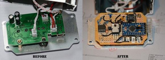
Taking the unit apart revealed a very convenient design for hacking. All of the components were connected to the main PCB by connectors, meaning the laser driver board was completely separate! He replaced the PCB completely using a prototyping board, an Arduino pro mini, a microphone with a simple preamp, a rotary encoder, and a MSGEQ7 chip to analyse the levels. Oh, and a MOSFET to control the motor via PWM output. It even ended up being close to the same size as the original!

If you happen to have one of these projectors and want to fix it too, he’s posted the source code and circuit diagram on github.

After the break, check out the before and after video. It’s still a cheap disco laser projector, but at least it works as advertised now!

Continue reading “Hacking A Disco Laser”

Taming STM32 Discovery Boards For Regular Use

taming-discovery-boards

We think [Karl Lunt] has a point when he says that the STM32 Discovery Boards are cool and inexpensive, yet not hobby friendly. But it’s nothing that a little big of creativity can’t solve. Above are pictured three of the hacks he used to tame the Discovery boards.

The first is the addition of a microSD card adapter. He soldered wirewrap wire to each of the contacts on the adapter. He recommends a low iron setting to make sure you don’t melt the plastic adapter housing. He then used double stick foam tape to adhere it to the bottom of the dev board. The other ends of the wire are wrapped around the appropriate pins on the dual-row pin header. Similarly, the UART3 connections are broken out from the pin headers to that white quick connect socket. This lets him access serial data without having to solve the USB issues that were vexing him.

Finally, he made his own daughter board to break out the dual row headers into screw terminals. We’ve been hit with problems interfacing hardware with the board’s native connections — jumpering to IDE cables just never worked reliably. This breakout board not only makes it simple, but organizes the pins into groups based on their alternate functions.

Do you remember seeing the hacksaw version of this Discovery board which gives you two dev boards for the price of one?

UDP Between STM32-F4 Discovery Boards

stm32-f4-udp

[The Backwoods Engineer] tested out a new accessory kit for the STM32-F4 Discovery board. The image above shows two boards communicating with the UDP protocol. Notice the extra PCB into which each Discovery board has been plugged. This is a third-party add-on which adds Ethernet, RS-232, SD card slot, and a connector for LCD or Camera. We’ve had one of these F4 Discovery boards on hand for a while and haven’t figured out a good way to connect external hardware to the huge dual pin-headers. This doesn’t solve the problem — the base board also includes dual headers to break-out all the pins — but having Ethernet, serial, and SD certainly reduces the need to add all that much more. The other drawback to the hardware is that the sample firmware is targeted at the IAR Embedded Workbench which is neither free, nor in the realm of affordable for hobbyists.

The NIC used on the baseboard has auto-crossover capabilities so the boards were connected using a regular Cat6 patch cable. This example has the boards constantly sending UDP packets with the module on the right reporting status information to a terminal via the serial connection.

In-depth Comparison At STM32 F3 And F4 Discovery Boards

The STM32 F3 and F4 Discovery boards have been around for a while now. We’ve looked at both separately and they’re impressive dev boards for the price. Now can get a closer look at each from this in-depth comparison of the two Cortex-M4 development tools.

To start off, both of the boards have the same size and footprint (there are two dual-row pin headers which break out the connections to the ARM chip). Fundamentally the F3 and F4 chips have a different level of features, but the boards themselves are aimed at different applications as well. The F3 series of microcontrollers looks to be more affordable than the F4, containing less program memory, no Ethernet capability, and only one USB port. But both have hardware floating-point abilities and they’re blazing fast. The boards offer a MEMS accelerometer for prototyping. But the Discovery-F3 also contains a gyroscope while the Discovery-F4 provides audio hardware like a microphone, and DAC.

If you want to use a Linux box to develop with these tools you might find this guide helpful.

.NET For The STM32 F4 Discovery Board

Here’s a technique that will let you use the .NET framework on an STM32 Discovery board. [Singular Engineer] was happy to learn that the .NET Micro Framework had been ported for STM32 chips. It’s doesn’t look like the port has hit a stable version yet, but these instructions will be enough to get you up and running. This lets you use managed code in the C# language to program an embedded device: the STM32 F4 Discovery board.

After flashing a new bootloader to the board a driver needs to be added for Windows to communicate with it. Above you can see that the board will enumerate as ‘STM32 .Net Test’. Once the driver is installed the rest of the firmware can be loaded on the board using a GUI supplied with the NETMF for STM32 package. That takes care of prepping the hardware, the rest is a painless process of configuring Visual Studio to use the board as a target. The ‘Hello World’ application then uses C# to blink an LED.

STM32 F4 Discovery Tutorial Using Open Source Tools

[Pulko Mandy] got his hands on the new STM32 F3 Discovery board. He’s a fan of the open source tools just like we are, so he posted a guide covering the use of an open source toolchain with the F3 hardware.

This board was just announced earlier this month but there is already support for it in OpenOCD. It’s not all that different from the F4 board, which we would think made the process a bit easier. [Pulko] is using the Sourcery CodeBench Lite toolchain, which works for pretty much all of the ARM chips out there. It is GCC based and comes with GDB for debugging (along with all the other tools you would expect). He did created his own Linker script and startup code. These are crucial for ARM so it’s nice that he provided them for us. He finishes up the guide by showing how OpenOCD can be used to flash the code to the chip and how it works with the debugger.

[Photo source]

STM32 F3 Discovery Dev Board Includes Some Extras

ST Microelectronics keeps kicking out development boards to show off their new ARM processor line. Yesterday they issued a press release announcing the STM32 F3 Discovery Board. As their naming scheme implies, this carries an ARM Cortex-M3 processor, but compared to the F0 Discovery board (which we loved) it’s got several extra goodies built into it.

We took a look at the F3 Discovery product page and it doesn’t look like you can order these quite yet. But click-through to the pricing and you’ll see they’ve set it at $10.90. Digikey lists the board at that price point, Mouser lists it at about $16, but neither supplier has any available. We also didn’t see a link for free boards like when the F0 model was released. If you do come across a giveaway link please tip us off about it.

Okay, now let’s discuss those extras. We think this dev kit could be used as an IMU for applications like a quadcopter or a self-balancing robot. That’s because it has a gyroscope and an accelerometer. It’s also got ten LEDs, eight of which are arranged on that white circle. We’d guess that layout is for displaying orientation data from the IMU sensors. There’s also a second USB port to use when developing USB applications for the chip.

Like the other boards in the Discovery family this has the STlinkV2 built-in to use as a programmer. We don’t know if OpenOCD has support for the F3 chipset yet, which is what we’ve been using to program STM chips in a Linux environment.