Discovering The Protocol In A USB VoIP Phone

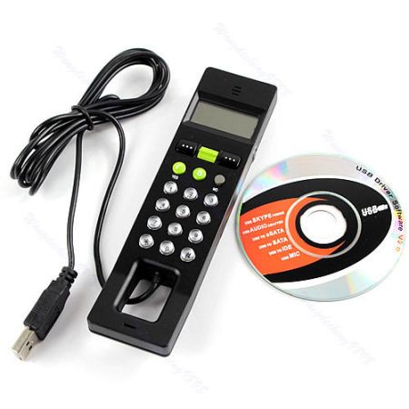
[Daniel] picked up a cheap USB handset to use with his VoIP provider, and included in the box was a CD with all the software that would make this handset work with Windows. [Daniel] is running Linux on his main battlestation, rendering the included CD worthless. Using the handset under Linux would be a problem; although the speaker and mic worked, the buttons and screen did not. No problem, then: [Daniel] just played around with the command line until he figured it out.

The handset presented itself to the Linux box as a soundcard and HID device. The soundcard was obviously the speaker and mic, leaving the buttons and display as the HID device. [Daniel] checked this out by running a hexdump on the HID device and pressed a few buttons. His suspicions were confirmed, and he could easily read the button with a little bit of Python.

With the speaker, mic, and buttons on the handset figured out, [Daniel] turned his attention to the one bit of electronics on the phone he hadn’t yet conquered: the display. After firing some random data at the phone, the display blinked and showed a messy block of pixels, confirming the display was controlled through the HID driver. Loading up usbsnoop to see what the original software does to update the screed showed [Daniel] the data format the display accepts, allowing him to control everything in this VoIP phone.

Developed On Hackaday: Discovering Shenzhen And Its Companies

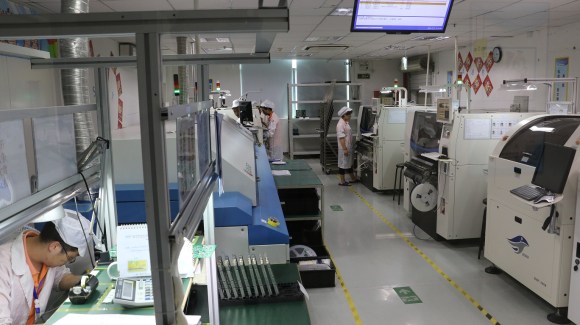
Assembly line in shenzhen

Two weeks ago we showed a first demonstration video of the offline password keeper (aka Mooltipass) the Hackaday community had been working on for the last 6 months. We received lots of interesting feedback from our dear readers and around a thousand of them let us know they were interested in purchasing the device. We agreed that preferential pricing should be offered to them, as they have been supporting this community driven project for so long.

For the next few days I will be touring Shenzhen and finally meeting the persons who have been assembling my electronics projects for the last 2 years, including the Mooltipass beta testers’ batch. I’ll also meet with Ian from Dangerous Prototypes, talk with the people behind the Haxlr8r program, visit Seeedstudio offices and a CNC shop. If everything goes well with the camera I just purchased in Hong Kong I should have nice things to show you. In the meantime, don’t hesitate to leave a comment below in case you’re in the area…

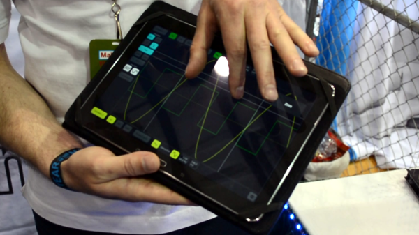
Showing the tablet interface for the scope

Discovering A Wifi Enabled 10MHz Oscilloscope

[youtube=https://www.youtube.com/watch?v=qEqWtKGJhFQ&w=580]


As most of our readers know, [Mike] was visiting Bay Area Maker Faire  last weekend with a big Jolly Wrencher on his back. During his tour he encountered the neat oscilloscope shown in the video above, made by the Belgian company Velleman. Even though it only has a 10MS/s sampling rate and a 10MHz bandwidth, our guess is that it may still be useful for some hobbyists out there as it can communicate with any PC/smartphone/tablet using its Wifi interface.

Inside the black box is a 3.7V 1800mAh Li-ion battery with a USB port to recharge it or update the oscilloscope’s firmware. As seen in the video, the tablet’s touchscreens may enable more natural interaction with the user interface. The protocol used to export the acquired samples is open, which may allow users to create their own analysis program. The oscilloscope uses an 8 bit analog to digital converter and a 4K samples buffer.

First Stab At Motion Sensor To Disconnect A Car Charger

motion-sensing-car-charger


[Pixel] just sent in this automotive hack which disconnects his car charger when the vehicle stops moving for at least 10 minutes. Why would you need such a thing? The 12V outlet in his vehicle isn’t disconnected when the ignition is turned off. If he leaves a charger plugged in when parking the car, he often returns to a drained battery.

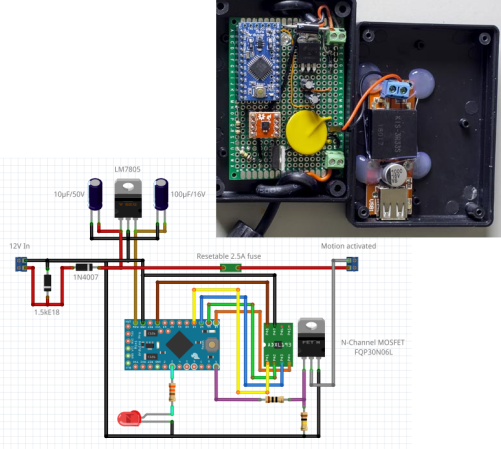
The fritzing diagram tells the story of this hack. He’s using a 7805 to power the Arduino mini. This monitors an ADXL362 accelerometer, starting the countdown when motion is no longer sensed by that chip. At the 10-minute mark the N-channel MOSFET kills the ground side of the outlet. Good for [Pixel] for including a resetable fuse on the hot side. But it was the diode all the way to the left that caught our eye. Turns out this is part of a filtering circuit recommended in a forum post. It’s a Zener that serves as a Transient-Voltage-Suppression diode.

Another comment on that thread brings up the issue we also noticed. The 7805 linear regulator is constantly powered. Do you think putting the uC into sleep and leaving the linear regulator connected is an adequate solution? If not, what would you do differently?

Retrotechtacular: Discovering Electronic Music

retrotechtacular-discovering-electronic-music

We take it for granted today that a lot of the music we hear includes synthesized instruments and sounds. But looking all the way back to 1983 for this Discovering Electronic Music video series provides a glimpse of the humble beginnings of the technology. The first five minutes of part one may annoy your aurally, but it’s worth it as that’s the point at which we get into sound generation using equipment like that seen above. All three parts in the series are embedded below; about twenty minutes of video in total.

Mixer boards and other control interfaces used today still have a large area of real estate devoted to knobs and adjustments. But they also include a ton of software processing options which weren’t available until computers became both affordable and ubiquitous. What’s shown in the video is a set of hardware interfaces that process signals from oscillators or alter recorded sound. We’ve spent a lot of time marveling about software defined radio and how it’s making RF hacking accessible to the masses. But who here hasn’t done at least a bit of tinkering in electronic music using any of the myriad of audio software? Would you have done that if you needed to build your own envelope and filter circuitry?

Continue reading “Retrotechtacular: Discovering Electronic Music”

Hacking A Disco Laser

hacked laser disco

[Mark] was looking for a cheap disco laser projector for parties, and he found one. Unfortunately for him, the advertised features were a bit lacking. The “sound activation mode” was merely an on off circuit, as opposed to it actually being controlled by the music — he set out to fix this.

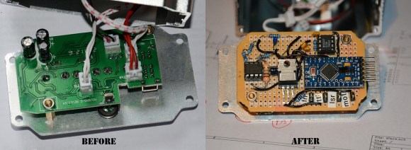
Taking the unit apart revealed a very convenient design for hacking. All of the components were connected to the main PCB by connectors, meaning the laser driver board was completely separate! He replaced the PCB completely using a prototyping board, an Arduino pro mini, a microphone with a simple preamp, a rotary encoder, and a MSGEQ7 chip to analyse the levels. Oh, and a MOSFET to control the motor via PWM output. It even ended up being close to the same size as the original!

If you happen to have one of these projectors and want to fix it too, he’s posted the source code and circuit diagram on github.

After the break, check out the before and after video. It’s still a cheap disco laser projector, but at least it works as advertised now!

Continue reading “Hacking A Disco Laser”

Taming STM32 Discovery Boards For Regular Use

taming-discovery-boards

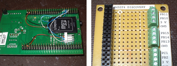
We think [Karl Lunt] has a point when he says that the STM32 Discovery Boards are cool and inexpensive, yet not hobby friendly. But it’s nothing that a little big of creativity can’t solve. Above are pictured three of the hacks he used to tame the Discovery boards.

The first is the addition of a microSD card adapter. He soldered wirewrap wire to each of the contacts on the adapter. He recommends a low iron setting to make sure you don’t melt the plastic adapter housing. He then used double stick foam tape to adhere it to the bottom of the dev board. The other ends of the wire are wrapped around the appropriate pins on the dual-row pin header. Similarly, the UART3 connections are broken out from the pin headers to that white quick connect socket. This lets him access serial data without having to solve the USB issues that were vexing him.

Finally, he made his own daughter board to break out the dual row headers into screw terminals. We’ve been hit with problems interfacing hardware with the board’s native connections — jumpering to IDE cables just never worked reliably. This breakout board not only makes it simple, but organizes the pins into groups based on their alternate functions.

Do you remember seeing the hacksaw version of this Discovery board which gives you two dev boards for the price of one?