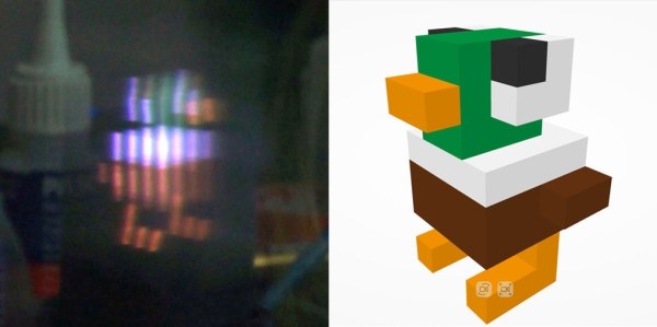
Persistence of vision projects are a dime a dozen, but by adding a third dimension [Madaeon] succesfully created one to stand out from the crowd. Instead of waving around a single line of LEDs, he is moving a 2D grid of them vertically to create a volumetric POV display.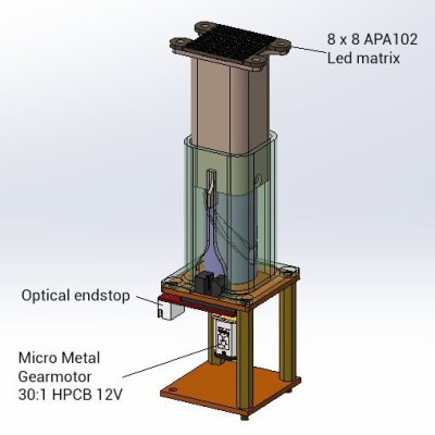
The display consists of oscillating 3D printed piston, powered by a small geared motor, on top of which sits a 8 x 8 RGB LED grid and diffusing film. The motor drives a cylindrical cam, which moves a piston that sits over it, while an optical end stop detects the bottom of the piston’s travel to keep the timing correct. [Madaeon] has not added his code to the project page, but the 3D files for the mechanics are available. The current version creates a lot of vibration, but he plans to improve it by borrowing one of [Karl Bugeja]’s ideas, and using flexible PCBs and magnets.
He also links another very cool volumetric display that he constructed a few years ago. It works by projecting images from a small DLP projector onto an oscillating piece of fabric, to created some surprisingly high definition images.
POV displays are good projects for learning, so if you want to build your own, take a look a simple POV business card, or this well-documented POV spinning top.