Tiny Function Generator On The ATtiny85, Complete With OLED

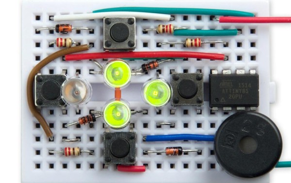
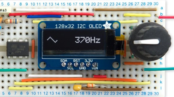
It’s easy to have a soft spot for “mini” yet perfectly functional versions of electronic workbench tools, like [David Johnson-Davies]’s Tiny Function Generator which uses an ATtiny85 to generate different waveforms at up to 5 kHz. It’s complete with a small OLED display to show the waveform and frequency selected. One of the reasons projects like this are great is not only because they tend to show off some software, but because they are great examples of the kind of fantastic possibilities that are open to anyone who wants to develop an idea. For example, it wasn’t all that long ago that OLEDs were exotic beasts. Today, they’re available off the shelf with simple interfaces and sample code.

The Tiny Function Generator uses a method called DDS (Direct Digital Synthesis) on an ATtiny85 microcontroller, which [David] wrote up in an earlier post of his about waveform generation on an ATtiny85. With a few extra components like a rotary encoder and OLED display, the Tiny Function Generator fits on a small breadboard. He goes into detail regarding the waveform generation as well as making big text on the small OLED and reading the rotary encoder reliably. His schematic and source code are both available from his site.

Small but functional microcontroller-based electronic equipment are nifty projects, and other examples include the xprotolab and the AVR-based Transistor Tester (which as a project has evolved into a general purpose part identifier.)

A Game That Does More With Less

[David Johnson-Davies] created a minimal Secret Maze Game using a single ATTiny85 and a few common components. This simple game uses four buttons, four LEDs, and a small speaker. The player moves in the four cardinal directions using buttons, and the LEDs show walls and corridors. If an LED is lit, it means the path in that direction is blocked by a wall, and attempting to move in that direction will make a beep. When the player reaches the exit, a short victory tune chirps from the speaker.

Sample maze. A 16×16 matrix is allocated for maze designs.

Since the ATTiny85 has only five I/O lines, [David] had to get a bit clever to read four buttons, display output on four LEDs, and drive a little speaker. The solution was to dedicate one pin to the speaker and the other four to charlieplexing, which is a method of driving more LEDs than you have pins. It takes advantage of the fact that most microcontroller pins can easily switch state between output high, output low, or low-impedance high-impedance input.

As for the buttons, [David] charlieplexed them as well. Instead of putting an LED in a charlieplexed “cell”, the cell contains a diode and an SPST switch in series with the diode. To read the state of the switch, one I/O line is first driven low and the other I/O line is made an input with a pullup. A closed switch reads low on the input, and an open switch reads high. With charlieplexing, four pins is sufficient for up to twelve LEDs (or buttons) in any combination, which is more than enough for the Secret Maze.

Charlieplexing is also what’s behind this 110 LED micro-marquee display, or this elegant 7-segment display concept that takes advantage of modern PCB manufacturing options.

Continuity Tester Uses The ATtiny85’s Comparator

There’s an inside joke among cyclists – the number of bikes you need is “n+1”, where “n” is your current number of bikes. The same probably also applies to the number of tools and equipment a hacker needs on their workbench. Enough is never enough. Although [David Johnson-Davies] has a couple of multimeters lying around, he still felt the urge to build a stand-alone continuity tester and has posted details for a super-simple ATtiny85 based Continuity Tester on his blog. For a device this simple, he set himself some tall design goals. Using the ATtiny85 and a few SMD discretes, he built a handy tester that met all of his requirements and then some.

The ATtiny85’s Analog Comparator function is perfectly suited for such a tester. One input of the comparator is biased such that there is a 51 ohm resistor between the input and ground. The output of the comparator toggles when the resistance between the other input and ground is either higher or lower than 51 ohms. Enabling internal pullup resistors in the ATtiny85 not only takes care of proper biasing of the comparator pins, but also helps reduce current consumption when the ATtiny85 is put to sleep. The test current is limited to 100 μA, making the tester suitable for use in sensitive electronics. And enabling the sleep function after 60 seconds of inactivity reduces standby current to just about 1 μA, so there is no need for a power switch. [David] reckons the CR927 button cell ought to last pretty long.

For those interested in building this handy tester, [David] has shared the Eagle CAD files as well as the ATtiny85 code on his Github repository or you could just order out some boards from OSHpark.