The Fascinating Evolution Of Micromouse

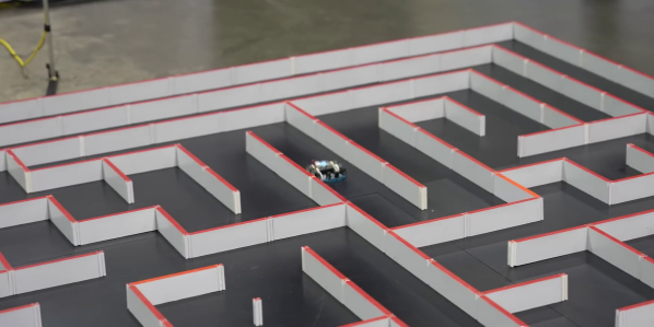
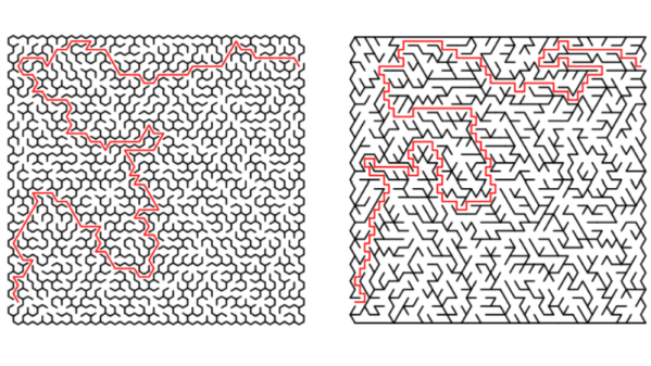
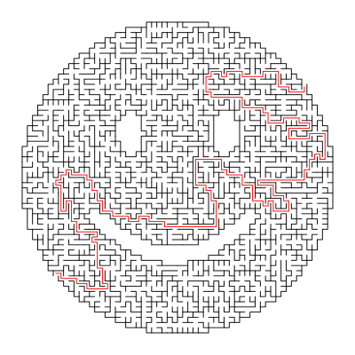
You would think there are only so many ways for a robotic mouse to run a maze, but in its almost 50 year history, competitors in Micromouse events have repeatedly proven this assumption false. In the video after the break, [Veritasium] takes us on a fascinating journey through the development of Micromouse competition robots.

The goal of Micromouse is simple: Get to the destination square (center) of a maze in the shortest time. Competitors are not allowed to update the programming of their vehicles once the layout is revealed at the start of an event. Over the years, there have been several innovations that might seem obvious now but were groundbreaking at the time.

The most obvious first challenge is finding the maze’s center. Simple wall following in the first event in 1977 has developed into variations of the “flood fill” algorithm. Initially, all robots stopped before turning a corner until someone realized that you could cut corners at 45° and move diagonally if the robot is narrow enough. The shortest path is not always the fastest since cornering loses a lot of speed, so it’s sometimes possible to improve time by picking a slightly longer router with fewer corners.

More speed is only good if you can keep control, so many robots now incorporate fans to suck them down, increasing traction. This has led to speeds as high as 7 meters/second and cornering forces of up to 6 G. Even specks of dust can cause loss of control, so all competitors use tape to clean their wheels before a run. Many winning runs are now under 10 seconds, which require many design iterations to increase controllable speed and reduce weight.

All these innovations started as experiments, and the beauty of Microhouse lies in its accessibility. It doesn’t require much of a budget to get started, and the technical barrier to entry is lower than ever. We’ve looked at another Micromouse design before. Even if they aren’t micromice, we can’t get enough of tiny robots.

Continue reading “The Fascinating Evolution Of Micromouse”

Finding Paths With Water Is A-Mazing

We aren’t sure if it qualifies as fluidic logic, but [Steve Mould] was inspired by a simulation of water flowing through a maze and decided to build some actual mazes and watch water flowing through them. It turns out there are several physical effects in play, and you can see [Steve] discuss them in the video below.

The maze, of course, has to be oriented so that water flows into the top and flows out of the bottom. Without much thought, you’d think that the water just goes to the bottom and then fills up. Eventually, the part that is open at the bottom will have water coming out, right? Turns out it isn’t that simple.

A combination of air pressure and surface tension conspire to make the water do better than expected. Not that it perfectly solves it, but it doesn’t just fill up the entire maze, either. Even more interesting is that once the water has found the bottom, changing the water color will clearly show the path through the maze since nearly all of the new colored water will follow the flow path.

Practical? We can’t think of why. But it is a great think piece on how water flows and what sort of forces can affect it.

[Steve] is no stranger to making water work out algorithms, something called fluidic logic.

Continue reading “Finding Paths With Water Is A-Mazing”

A Number Maze For Younger Hackers

[David Johnson-Davies] has a lofty goal of building a small device to give to younger hackers on a semi-yearly basis. So this last year, he designed and created The Number Maze Game, a small handheld logic puzzle maze.

It’s based on several 4-digit seven-segment displays controlled by an AVR128DA32. Navigation is just a few push buttons and a buzzer to let you know when you’ve won. The game is simple: you jump the amount listed on the space you’re currently on, trying to get to the space labeled “H.” [David] lays out how he built it in great detail, discussing the process of designing and assembly. He also expounds on many decisions, such as using a TQFP microcontroller instead of the through-hole ATmega328P due to the I/O pin count.

The instructions and design process are so detailed we’re confident most people could easily reproduce it, especially with the code and board files. But the value of this project is not in blindly copying it. Instead, we love how something so simple can be wonderfully entertaining and valuable to younger hackers. Programming headers are included so they can add new mazes. We suspect there are many out there who would love to get something so tactile, simple, and modifiable.

Of course, we’ve seen other minimal maze games, so there’s no lack of inspiration for making some different.

Complicated Calculated Solution To 3D-Printed Puzzle

3D printers have made a lot of things possible that were either extremely difficult or downright impossible with traditional tooling. Certain shapes lend themselves to 3D printing, and materials and tooling costs are also generally greatly reduced as well. One thing that may not be touched on as often, though, is their ability to rapidly prototype solutions to complex mathematical problems, in this case taking the form of a 3D printed maze, known as a dodecahedral holonomy maze, with an interesting solution.

The puzzle presents itself as a sphere composed of various inlaid hexagons which form a track for the puzzle piece, or “rook”. The tracks create the maze for the rook to travel, as some paths are blocked when the rook is oriented in certain ways. To solve the puzzle, the player must rotate the rook by moving it around the hexagons in such a way that its path isn’t physically blocked by any of the pegs in order to successfully reach the exit. This might seem like a fun toy to have on its surface, but the impressive thing about this is that the solutions are designed to reduce the likelihood of solving the puzzle with any “brute force” methods while at the same time having more than one path that will reach the exit as well as several bottlenecks that the puzzle solver must traverse as well.

There are actually many possible puzzles that can be produced in this size and shape, and all have predetermined solutions with cleverly chosen paths. This might seem like a lot but when you realize that the entire build from concept to 3D modeling to implementation was done by [Henry Segerman] and a group of other mathematicians at Oklahoma State University it starts to become more clear how the puzzle was so well-designed. In fact, we’ve featured some of his other mathematically-modeled builds in the past as well.

Thanks to [Inne] for the tip!

Continue reading “Complicated Calculated Solution To 3D-Printed Puzzle”

Maze Solving Via Text Editing

Linux scripters usually know about sed — the stream editor. It has a simple job: transform text as it whizzes from input to output. So if you wanted to solve a maze, this wouldn’t be the tool you’d think to use, right? Well, if you were [xsot], you’d disagree.

You build a maze using spaces for empty space and # for walls. There’s an S to mark the start position and an E to mark the end. Of course, the maze can also contain newlines. The sed script does an amazing job of solving the problem.

Continue reading “Maze Solving Via Text Editing”

Maze Generator Keeps Plotter (and Kids) Busy

We can tell that [Jon Howell] is our kind of guy. After updating his vintage 1985 Hewlett-Packard plotter with WiFi and the ability to load SVG files, he obviously needed to find a bunch of stuff to run off with it. Gotta justify those hacks somehow. So he doubled down and decided support a hack with another hack by writing a maze generator to keep his plotter well fed. He was kind enough to unleash his creation on an unsuspecting Internet as an open source project, and now we all can benefit from a couple of reams worth of mazes.

The generator itself is written in Java, and should work on whatever operating system your box happens to be running thanks to the *nix and Windows wrapper scripts [Jon] provides. To create a basic maze, one simply needs to provide the script with the desired dimensions and the paper size. You can define the type of paper with either standard sizes (such as --paper a4) or in the case of a plotter with explicit dimensions (--paper 36x48in).

If you aren’t a big fan of right angles, there’s support for changing the internal geometry of the maze to use a hexagonal or triangle grid. You can even pass the program a black and white PNG “mask” which it will use as the boundaries for the maze itself, allowing for personalized puzzles of whatever shape catches your fancy. [Jon] even ran the Wrencher though his software, leading to the creation of a maze which we can neither confirm nor deny will be making an appearance on our Christmas cards this year.

Whether you need to prove to your significant other that the hours you spent fiddling with your plotter are well spent, or an easy way to entertain the junior humans in your life, you can thank [Jon] for your solution.

Pic16maze secret maze game

PIC16Maze Upgrades Secret Maze Game

We really like it when a reader is inspired by something they see on Hackaday, build on it, and let us know so we can pass it on. In this case, [Vegipete] made a secret maze game using a minimal number of parts and some neat software trickery.

It’s built around an 8-pin PIC16F18313 microcontroller, uses a joystick for input, and nine WS2812 LEDs to display the player and the surrounding maze walls. His inspiration was [David Johnson-Davies’] minimalist secret maze game built around the 8-pin ATTiny85. In that one, [David] cleverly used charlieplexing to get four pins to control four LEDs and four pushbuttons. [Vegipete’s] use of the WS2812 LEDs allowed him to control the LEDs with just one pin, and also get color while using three pins for the joystick and its button. He may use another pin in the future for sound and vibration.

He goes into some detail on the WS2812 protocol, how communication is done with the LEDs using just one pin and different pulse-lengths to represent 0 and 1. We’ll leave you to see his post for more depth but basically, he introduces a module on the PIC called the Configurable Logic Cell (CLC) which makes this easy and frees up processor cycles for the user’s code to do other things.

Secret maze wall bits
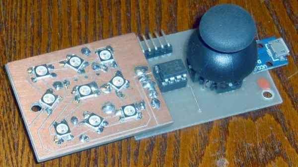
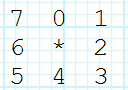
His source code is available on request but he does detail a neat software trick he uses for rotating the view. It may be confusing for some but as you move through the maze, your viewpoint rotates so that up is always the direction you’re facing. Luckily, the walls surrounding the user can be represented using 8-bits, four for east, west, north, and south, and four more for the corners. The maze is stored as a bitmap and from it, 8-bit values are extracted for the current position, each bit representing a wall around the position. To rotate the walls to match the user’s current orientation, the bits are simply shifted as needed. Then they’re shifted out to set each LED. Check it out in the video below.

It works very well despite the minimal interface and part count.

Continue reading “PIC16Maze Upgrades Secret Maze Game”