Following Faces With OpenCV And Arduino

[youtube=http://www.youtube.com/watch?v=lD4uFD7j0AU&w=470]

[Marco] has had some fun with OpenCV in the area of face tracking. Using an older laser project, he has cobbled together a system that will track a face and put a laser on it. While he is just using this as a proof of concept, it goes without saying that you probably shouldn’t mount a laser on a face tracker. However, stuffing this into a myKeepon wouldn’t be a horrible thing.

[Marco] shares the process of getting the OpenCV bit working in this writeup, you’ll have to refer back to his laser gun project for the physical build.


[via Adafruit]


A Light-Following Pong Game

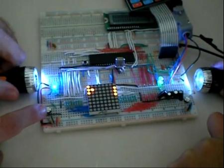
Although not everyone has the ability to make a hacked Pong game Like [Marcelo], even fewer have the ability or the creativity to come up with the elaborate hack that he did. The basic premise of his game is a version of pong played on a breadboard with a 8×8 matrix of LEDs. The controls are really what sets this hack apart. Instead of using a paddle controller or normal switches, small flashlights are used to control the on-screen (on-LED matrix) paddle. This is accomplished using a series of photoresistors and a PIC processor.

Innovative as this would be by itself, [Marcelo] decided to make a program in Flash to display the action on a computer.  Communication is done serially, and C# is used to translate everything as Flash doesn’t natively work with a serial connection.

Another innovation is that there are two LEDs connected on either side powered via pulse width modulation. The lights get dimmer as one player is about to lose. Check out [Marcelo’s] pong game after the break!

Continue reading “A Light-Following Pong Game”

Matchbox-sized Line Following Robot

pocketbot_line_following_robot

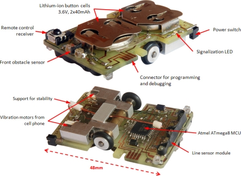
While they are not nearly as complex as their self-navigating brethren, building line following robots is no simple task, especially when they are this small. The creation of [Ondřej Staněk], this matchbox-sized line following robot is quite impressive.

PocketBot’s 48mm x 32mm circuit board also acts as its frame, supporting the wheels, motors, microcontroller and more. The brains of the operation is an ATmega8 microcontroller mounted on the bottom of the bot. A pair of wheels are driven independently using a set of mobile phone vibration motors that power the bot at speeds of up to 0.35 meters per second. Line detection is achieved by using three different IR sensors paired with four IR emitters located at the front end of the bot.

PocketBot also has an IR receiver on its top side, which allows [Ondřej] to control the robot, tweak its parameters, or calibrate its sensors on the fly using an IR remote or his computer.

The PocketBot might not be the absolute smallest line following bot we’ve seen, but it’s pretty darn close!

Continue reading to see PocketBot in action.

Continue reading “Matchbox-sized Line Following Robot”

Making A Line-following Toy Into A Programmable Robot

[Eric Gregori] picked up this little yellow robot as a kit build. It has a single PCB inside that has a pair of IR emitters and detectors pointed downward at the front of the robot. It is able to follow a dark line on a light surface based on how the infrared beam reflects back to the detector. But it’s a one-trick pony that [Eric] wanted to make into a programmable robot.

The kit came with a schematic, which makes the process of patching into its logic quite easy. There are two motors, each with a driver circuit made up of a pair of transistors and one flyback diode. This means the motors can only move in one direction, but they also only take one logic connection to control. Instead of populating the transistor that usually connects the IR receiver to the motor driver, [Eric] soldered jumper wires from each to an MSP430 chip (the G2231 that came with his Launchpad).

As you can see in the clip after the break, the first version of the code he wrote makes the robot follow a line as it would if it had not been altered. But there’s still plenty of programming space and several free I/O pins for future improvements.

Continue reading “Making A Line-following Toy Into A Programmable Robot”

One Really Big Quadcopter That Is Following In The Steps Of The Spruce Goose

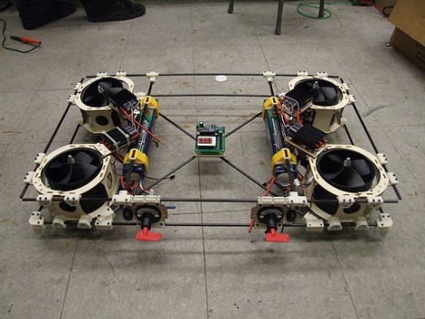
Behold the Land-Bear-Shark, a quadcopter on a rather grand scale. At a full eight kilograms it’s an easy target to compare the [Howard Hughes] behemoth, but in addition to the weight, this still has yet to make its first flight.

To give you some scale to the image above, the board at the center is an Arduino. It controls the beast, along with the help of a SparkFun IMU board which rides atop. Really, if any quadcopter of this size has a chance of working, this should be the one. The construction is beautiful, making use of carbon fiber rod along with 3D-printed connectors to assemble the frame. A lot of thought has gone into small things like conserving weight used on the landing gear, which are incorporated into the bottom corner brackets. The batteries are connected in a manner that makes them easy to adjust, acting as ballast for balancing the craft.

We’re keeping our fingers crossed that this will be more than the tongue-in-cheek title of the post which calls it a Quadrotor-shaped sculpture.

[via Adafruit]

Nimbus, The Wall-following Robot

nimbus_wall_following_robot

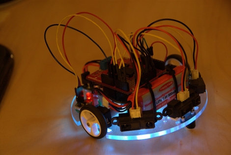
[Johannes] sent in the latest iteration of an ongoing project – Nimbus, the wall-follwing robot. Originally operating on a cardboard frame, the robot has undergone several revisions as you can see by reading through his blog. Nimbus started out as a simple, Arduino-powered robot, but the project has progressed nicely over time. The last revision simply avoided walls, using a Sharp IR proximity sensor to detect, then avoid obstacles. The most recent model sports a nice polycarbonate frame as well as two additional IR proximity sensors, allowing Nimbus to navigate quite well, following walls and avoiding obstacles with ease. It does get caught up from time to time on carpets and wires, but overall Nimbus is a great little robot. [Johannes] even added a small RGB status LED for the bottom of the bot, communicating its navigation status to the operator at all times. This is done by flashing various colors when objects have been discovered or have moved out of sight – it’s a really novel addition.

Keep reading for a video of Nimbus navigating his way around, and don’t forget to check out the Nimbus photo stream.

Continue reading “Nimbus, The Wall-following Robot”

Line Following Tank Without A Microcontroller

This line following tank uses analog circuitry to sense where a dark line is and adjust its course. Despite the opening paragraph on the schematic page (which looks to be leftover from a past project writeup) this circuit relies on a set of transistors for motor control. [Chris] does a great job of explaining the setup in detail; it boils down to a phototransistor detecting reflected light and flipping which motor is running based on what is detected. A couple of potentiometers are included to tune up the accuracy of the circuit. There’s a short clip of the treaded-terror making a loop around the track after the break.

This is another great way to try your hand at analog circuitry. Once you’ve built the body (tank or otherwise) and line tracking circuit it can be repurposed by swapping out the brains for your next project.

Continue reading “Line Following Tank Without A Microcontroller”