Line Following Robot Without The Lines

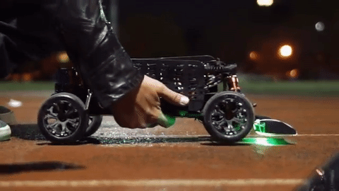
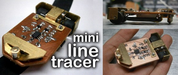
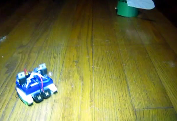
Line-following robots are a great intro to robotics in general, since the materials and skills needed to build a good one aren’t too advanced. It turns out that line-following robots are more than just a learning tool, too. They’re pretty useful in industry, but most of them don’t follow visible marked lines. Some, like this inductive guided robot from [Randall] make use of wires to determine their paths.

Some of the benefits of inductive guidance over physical lines are that the wires can be hidden in floors, so if something like an automated forklift is using them at a warehouse there will be less trip hazard and less maintenance of the guides. They also support multiple paths, so no complicated track switching has to take place. [Randall]’s robot is a small demonstration of a larger system he built as a technician for an autonomous guided vehicle system. His video goes into the details of how they work, more of their advantages and disadvantages, and a few other things.

While inductive guided robots have been used for decades now, they’re starting to be replaced by robots with local positioning systems and computer vision. We’ve recently seen robots that are built to utilize these forms of navigation as well.

Continue reading “Line Following Robot Without The Lines”

Line Following Robot Trains Runners

Can your line following robot move faster than [Usain Bolt] who has been described as “The World’s Fastest Timed Human”? Puma, the athletic footwear, apparel and accessories company, created such a robot to help train their company sponsored athletes.

The shoebox-sized robot exceeds [Bolt]’s top speed of 44-km/hour. At that speed, following a line gets tricky. It took the development team 8 prototypes to attain that capability. Inside the BeatBot an Arduino reads 9 infrared sensors for line detection at 100 samples a second. A digital servo controls the Ackerman steering mechanism to follow the line on the track or floor. Wheel encoders provide the data for speed and distance measurement.

The user can set the distance of the run and the time to beat. Run pacing can also be adjusted. LEDs on the robot provide the starting ‘gun’ and help the runner see the BeatBot using peripheral vision. Two GoPro cameras, front and rear, provide a visual record of the run.

Puma believes that actually running against a competitor, even a robot, improves performance more than just running against the clock. They’re betting a grown-up line follower will help Olympic class athletes improve their performance. Continue reading “Line Following Robot Trains Runners”

Autonomous Vehicle-Following Vehicle

Humanity has taken one step closer to Skynet becoming fully aware. [Ahmed], [Muhammad], [Salman], and [Suleman] have created a vehicle that can “chase” another vehicle as part of their senior design project. Now it’s just a matter of time before the machines take over.

The project itself is based on a gasoline-powered quad bike that the students first converted to electric for the sake of their project. It uses a single webcam to get information about its surroundings. This is a plus because it frees the robot from needing a stereoscopic camera or any other complicated equipment like a radar or laser rangefinder. With this information, it can follow a lead vehicle without getting any other telemetry.

This project is interesting because it could potentially allow for large convoys with only one human operator at the front. Once self-driving cars become more mainstream, this could potentially save a lot of costs as well if only the vehicle in the front needs the self-driving equipment, while the vehicles behind would be able to operate with much less hardware. Either way, we love seeing senior design projects that have great real-world applications!

Continue reading “Autonomous Vehicle-Following Vehicle”

A Mini Op-Amp Based Line Following Robot

LineRobot

There’s no denying it. Super small robots are just cool. [Pinomelean] has posted an Instructable on how to create a mini line following robot using only analog circuitry. This would make a great demo project to show your friends and family what you’ve been up to.

Analog circuitry can be used instead of a microcontroller for many different applications, and this is one of them. The circuit consists of two op-amps that amplify the output of two phototransistors, which control each motor. This circuit is super simple yet very effective. The mechanical system is also quite cool and well thought out. To keep things simple, the motors drive the wheel treads, rather than directly through an axle. After the build was completed, the device needed to be calibrated by turning potentiometers that control the gain of each op-amp. Once everything is balanced, the robot runs great! See it in action after the break.

While not the smallest line follower we have seen, this robot is quite easy to reproduce. What little robots have you build lately? Send us a tip and let us know!

[via Embedded Lab]

Continue reading “A Mini Op-Amp Based Line Following Robot”

Android+Arduino – Face Following RC Car

androidRCcar_01_14

To some of us, hacking an RC Car to simply follow a black line or avoid obstacles is too easy, and we’re sure [Shazin] would agree with that, since he created an RC Car that follows your face!

The first step to this project was to take control of the RC Car, but instead of hijacking the transmitter, [Shazin] decided to control the car directly. This isn’t any high-end RC Car though, so forget about PWM control. Instead, a single IC (RX-2) was found to handle both the RF Receiver and H-Bridges. After a bit of probing, the 4 control lines (forward/back and left/right) were identified and connected to an Arduino.

[Shazin] paired the Arduino with a USB Host Shield and connected it up with his Android phone through the ADB (Android Debug Bridge). He then made some modifications to the OpenCV Android Face Detection app to send commands to the Arduino based on ‘where’ the Face is detected; if the face is in the right half of the screen, turn right, if not, turn left and go forward.

This is a really interesting project with a lot of potential; we’re just hoping [Shazin] doesn’t have any evil plans for this device like strapping it to a Tank Drone that locks on to targets!

Continue reading “Android+Arduino – Face Following RC Car”

Protoboard Line Following Robot

dspic-line-follower

We love a good line-following robot project and this really hits the spot. It’s got sharp edges, gobs of solder bridging, and look at all those jumper wires! Despite its appearance it puts in a performance that won’t disappoint.

It uses a dsPIC33 to read from half a dozen analog sensors on the bottom of the board. We’re not all that familiar with the chip’s features, but [Exapod] says it’s got an auto-scan feature he uses to read the sensors. This allows him to sample with 12-bit resolution from all six of them at about 30 kHz. No wonder the thing is so responsive in the demo video embedded below. The track he’s using is just some white printer paper with a fat circuit of black electrical tape placed in a somewhat squiggly pattern.

This is also a fun challenge with toys. Here’s one that hacks a hexapod to follow the lines.

Continue reading “Protoboard Line Following Robot”

Build A Light Following Bristlebot As A Way To Teach Science

light-following-bristlebot

[Ben Finio] designed this project as a way to get kids interested in learning about science and engineering. Is it bad that we just want to build one of our own? It’s a light following bristlebot which in itself is quite simple to build and understand. We think the platform has a lot of potential for leading to other things, like learning about microcontrollers and wireless modules to give it wireless control.

Right now it’s basically two bristlebots combined into one package. The screen capture seen above makes it hard to pick out the two toothbrush heads on either side of a battery pack. The chassis of the build is a blue mini-breadboard. The circuit that makes it follow light is the definition of simple. [Ben] uses two MOSFETs to control two vibration motors mounted on the rear corners of the chassis. The gate of each MOSFET is driven by a voltage divider which includes a photoresistor. When light on one is brighter than the other it causes the bot to turn towards to the brighter sensor. When viewing the project log above make sure to click on the tabs to see all of the available info.

This directional control seems quite good. We’ve also seen other versions which shift the weight of the bot to change direction.

Continue reading “Build A Light Following Bristlebot As A Way To Teach Science”