Giving Digital Calipers Bluetooth

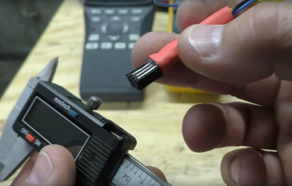
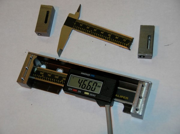
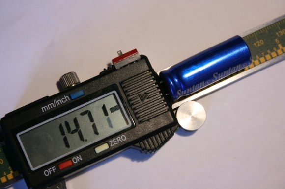
[Fede]’s wife uses a pair of digital calipers to take measurements of fruits, leaves, and stems as part of her field research. Usually this means taking a measurement and writing it down in a log book. All things must be digitized, so [Fede] came up with a way to wirelessly log data off a pair of cheap Chinese calipers with a custom-made Bluetooth circuit.

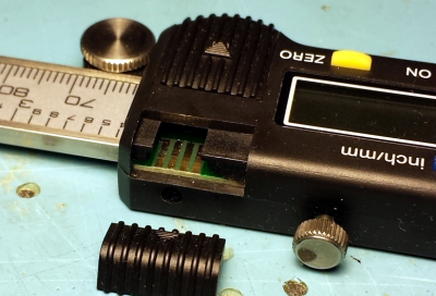
Most of these cheap Chinese digital calipers already have a serial output, so [Fede] only needed to build a circuit to take the serial output and dump it in to an off-the-shelf Bluetooth module. He fabbed a custom circuit board for this, and after seeing the increased battery drain from the Bluetooth module, decided to add an external battery pack.

In addition to etching his own board for sending the serial output of the calipers to a Bluetooth module, [Fede] also put together a custom flex circuit to connect the two boards. It’s just a small bit of brass glued to a transparency sheet etched with ferric chloride, but the end result looks amazingly professional for something whipped up in a home lab.

Talking Digital Calipers Make Engineering More Accessible

talking-digital-calipers

The team over at NerdKits recently put together a device aimed to help make the process of measuring things more accessible to those with disabilities. [Terry Garrett] is a Mechanical Engineering student, and as anyone who is in the field knows, it’s a discipline which requires taking tons of measurements. Since [Terry] cannot see he was often asking classmates to assist in measuring items during labs, but when he got a job at a nearby design studio, he knew he would have to find a way to take those measurements on his own.

Enter NerdKits.

[Humberto] wrote in to share how he and his team built a set of talking digital calipers to assist [Terry] in his daily tasks. They based the design off a previous project they worked on, getting digital readout data from a set of calipers. The DRO information is fed into an ATmega382p, which pieces together pre-recorded sound bites to announce the size of the object being measured.

As you can see in the video below, the system looks to work very well, and [Terry] is quite pleased with his new talking tool. We love seeing these sorts of hacks, because they truly make a difference in people’s lives – excellent job!

Continue reading “Talking Digital Calipers Make Engineering More Accessible”

Hold, Fast, And Max Features On A Digital Caliper

While adding an RJ-11 connector to his digital calipers [BadWolf] slipped, shorting out a pin and accidentally discovered new features. He intended to add a port for reading measurement data electronically, but after the slip-up an ‘H’ appeared on the LCD screen and the measurement was frozen at the same number. At first it seemed like he may have killed the device, but this is actually a hold function. A little bit more playing around and he discovered that a combination of button presses can also enable a fast function which speeds up the rate at which the display changes its reading. There is even a max function that only updates the display if the reading is higher than any previously displayed measurement. These are nice features which he uses by connecting a momentary push switch between two of the output pins, details we gleaned from the annotated video after the break. He doesn’t say which pins work for him, but we’d bet one of them is the ground pin on the port, and the other is one of the two data pins. Do some investigating with your own calipers and let us know what you find in the comments.

Continue reading “Hold, Fast, And Max Features On A Digital Caliper”

Reading A Digital Caliper With A Microcontroller

[Maris] wanted a way to read measurements from a digital caliper electronically. He ended up using the TI Launchpad to accomplish this, but not all of the necessary hardware is seen above. The calipers cost him about $7 on eBay, and they have four interface pins which made this hack quite a bit easier. After a bit of probing he established their purpose; voltage, ground, clock and data. A bit of scoping proved that data was being sent in 24-bit burst in packets that are quite easy to decode.

From there it’s just a matter of interfacing with a microcontroller. The chip he’s using is an MSP430G2231 that runs at 3.3V, but the caliper’s logic high is only 1.5v. By constructing an adapter using a pair of transistors, the data and clock from the calipers are able to pull pins on the MSP430 low. This is collected and analyzed by [Maris’] firmware and can be read on a PC using a terminal program.

[Thanks Chris]

Digital Caliper Modding


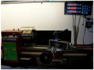
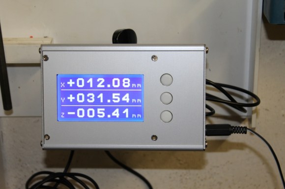
This particular hack is actually used in a kit design, but it’s still pretty sweet. This is a digital read out unit that’s a kit sold by shumatech. I’ve even mentioned it in passing before. The design takes in the pulses from inexpensive chinese made digital scales/calipers, and allows one stop calibration and ouput of three axis’s of measurement. Using the interface and a usb enabled pic, and you could make your own usb digital calipers… (Hmm, I might have to make some.)

A thickness gauge, letter scale, push stick, and dial caliper

Measure Three Times, Design Once

Most of the Hackaday community would never wire a power supply to a circuit without knowing the expected voltage and the required current. But our mechanical design is often more bodged. We meet folks who carefully budget power to their microcontroller, sensors, and so on, but never measure the forces involved in their mechanical designs. Then they’re surprised when the motor they chose isn’t big enough for the weight of their robot.

An obstacle to being more numbers oriented is lack of basic data about the system. So, here are some simple tools for measuring dynamic properties of small mechanisms; distances, forces, velocities, accelerations, torques, and other things you haven’t thought about since college physics. If you don’t have these in your toolkit, how do you measure?

Continue reading “Measure Three Times, Design Once”

A Vernier Take On A 3D Printer Extruder Indicator

A common way to visualize that a 3D printer’s extruder motor — which feeds the filament into the hot end — is moving is to attach a small indicator to the exposed end of the motor’s shaft. As the shaft turns, so does the attached indicator.

Small movements of the motor are therefore turned into larger movements of something else. So far, so simple. But what about visualizing very small extrusions, such as those tiny ones made during ironing?

[Jack]’s solution is a Vernier indicator for the extruder. Even the smallest movements of the extruder motor’s shaft are made clearly visible by such a device, as shown in the header image above. Vernier scales are more commonly found on measurement tools, and the concept is somewhat loosely borrowed here.

The usual way these lightweight indicators are attached is with a small magnet, and you can read all about them and see examples here.

This new design is basically the same, it simply has a background in a contrasting color added into the mix. [Jack]’s design is intended for the Bambu A1 printer, but the idea can be easily adapted. Give it a look if you find yourself yearning for a bit more visibility in your extruder movements.