Precision DIY Calipers? That’s A Moiré!

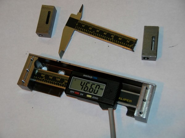
Moiré patterns are a thing of art, physics, and now tool design! [Julldozer] from Mojoptix creatively uses a moiré pattern to achieve a 0.05 mm precision goal for his custom designed 3D printed calipers. His calipers are designed to validate a 3D print against the original 3D model. When choosing which calipers are best for a job, he points out two critical features to measure them up against, accuracy and precision which he explains the definition of in his informative video. The accuracy and precision values he sets as constraints for his own design are 0.5 mm and 0.05 mm respectively.

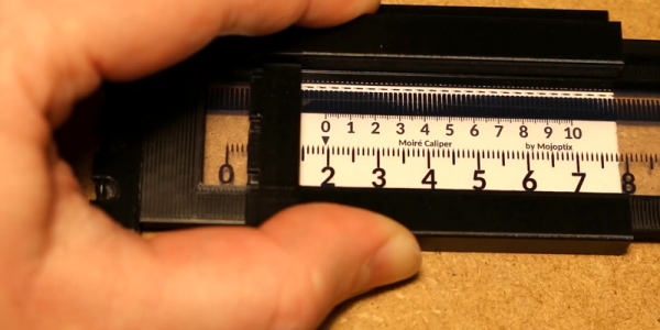
By experimenting with different parameters of a moiré pattern: the scale of one pattern in relation to the other, the distance of the black lines on both images, and the thickness of black and white lines. [Julldozer] discovers that the latter is the best way to amplify and translate a small linear movement to a standout visual for measurement. Using a Python script which he makes available, he generates images for the moiré pattern by increasing line thickness ratios 50:50 to 95:5, black to white creating triangular moiré fringes that point to 1/100th of a millimeter. The centimeter and millimeter measurements are indicated by a traditional ruler layout.

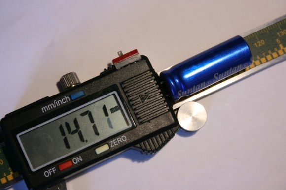
Looking for more tool hacks and builds? Check out how to prolong the battery life of a pair of digital calipers and how to build a tiny hot wire foam cutter.


Continue reading “Precision DIY Calipers? That’s A Moiré!”

The Most Sensational Calipers On The Planet!

Everyone here probably has a pair of cheap Chinese calipers kicking around the workbench. This means everyone here also knows how quickly the batteries in these handy little tools die. [Thosnbn] also noticed this, but instead of simply complaining and wishing the problem would go away, he decided to do something about it. He built a battery pack for his calipers, giving this tool a two year battery life.

The idea for this build came after [thosnbn]  completely destroyed a pair of these cheap calipers. At the time, the fix was to tape a AA battery to the tool, and solder wires directly to the contact pads for the tiny button cell battery. This fix worked, and after dealing with the ugliest tool known to man for a few years, [thosnbn] decided to clean it up a little.

The new battery enclosure was designed in Fusion360, includes handy features like a switch, and is completely 3D printed. It took a few weeks for [thosnbn] to get all the parts to fit together correctly, but the end result is great. This battery pack fits neatly on the back of the calipers, holds a single AA battery, and the lid is tightly secured with a pair of machine screws.

Unfortunately, [thosnbn] chose to share this project on imgur, a site that does not support sharing .stl or other 3D printer files. It does, however, serve as inspiration for you to make your own battery pack for a pair of cheap calipers.

Improved Digital Caliper Interfacing, Including 3D Printed Connector

[MakinStuff] wrote in to let us know about a project he did for new and improved interfacing to the ubiquitous cheap Chinese digital calipers. Interfacing to this common caliper model is well-trod ground, but his project puts everything about interfacing and reading the data in one place along with some improvements: a 3D printed connector that makes mating to the pads much more stable and reliable, 3d-printed-plug-for-digital-calipers
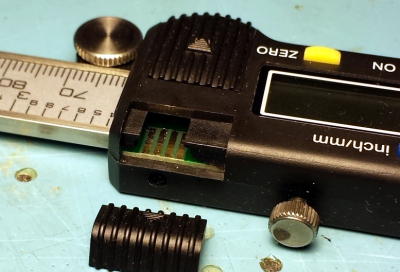
a simple interface circuit for translating the logic levels, and an interrupt-driven sample Arduino sketch to read the data. Making the sketch interrupt-driven means the Arduino never sits and waits for input from the calipers, making it easier have the Arduino do other meaningful work at the same time, ultimately making it easier to incorporate into other projects.

The connector has spaces to insert bare wires to use as contacts for the exposed pads inside the calipers. Add a little hot glue and heat shrink, and you’ll never have to fiddle with a hacked-together connection again.

This common caliper model has been hacked and re-purposed in interesting ways. We’ve seen them used as a Digital Read Out (DRO) on a lathe as well as being given the ability to wirelessly log their data over Bluetooth.

Continue reading “Improved Digital Caliper Interfacing, Including 3D Printed Connector”

Trinket EDC Contest: USB Calipers

[Lou]’s entry for the Trinket EDC Contest is a great addition to the ubiquitous digital calipers found on workbenches and eBay resellers the world over. It translates the value displayed on the calipers to a USB HID interface for logging all those tricky measurements at the push of a button.

Most of the digital calipers you’ll find at Harbor Freight or on eBay are pretty much the same. There are two pads on the caliper’s PCB that give any microcontroller the ability to read what is being measured. It’s done with a 24-bit encoding scheme, where each bit is a nearly-BCD measurement in units of 1/1000 of an inch or 1/100 of a millimeter. After decoding the value, [Lou]’s trinket sends a few numbers to a computer over a USB HID interface.

Simply sending a measurement to a computer over USB wasn’t enough for [Lou]. He added three buttons to the project for typing multiple characters. The first button just sends Enter to the computer, the second sends a comma, and the third sends “/2 (Enter)”, exactly what you need to input the radius of something when measuring the diameter.

This was a project for the Trinket EDC Contest that ended a few hours ago. Nobody knows who the winner is, but there are some pretty cool prizes up for grabs including the new Rigol scope, a Fluke 179, and a soldering station.

DIY Lathe DRO

Digital Caliper Sacrificed For DRO Project

In general, machining metal on a lathe or mill takes skill and patience as the accuracy of the cuts are important. To make those accurate cuts, it is important to know where the tool is located and how far it moves. For manual machines, the most basic method of determining position is by using graduated dials mounted on the hand cranks. Although these graduated dials can certainly be accurate, they may be difficult to see and they also require the operator to do math in their head on the fly with every full revolution of the dial. Another option would be a digital read out (DRO) which has an encoder mounted to the moving axes of the machine. This setup displays the exact position of the tool on an easy to read numeric display.

Professional DRO kits for mills and lathes can cost between a few hundred dollars to several thousand dollars.  [Robert] has a lathe, wanted a DRO but didn’t want to shell out serious cash to get it. He built his own for super cheap in an extremely resourceful way…. using a Harbor Freight Digital Caliper. A housing was first fabricated so that the added equipment would not hinder the axis travel of the lathe. The caliper was then cut to length, installed in the housing and the entire assembly was then mounted to the lathe.

DIY Lathe DRO
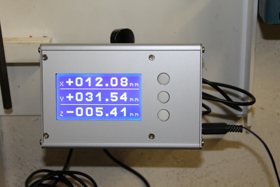
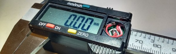
It is totally reasonable to use the stock caliper display to read the positional information, however, even these cheap digital calipers have connections for the encoder output data, which can easily be read by a microcontroller. That means it is super simple to hook these low-cost digital calipers up to a display remotely located in a more convenient position.


Three Axis Position Indicator With Digital Calipers

[Malte] just finished a little project for his Wabeco F1200 milling machine: a compact external display for three digital sliding calipers (Translated from German). As you may have already guessed, [Malte] was lucky enough to be able to fit disassembled calipers onto the machine and use them for positioning. Before embarking on this adventure, he noticed that there were similar projects present on the internet, but all of the calipers used had different data interfaces and protocols. The calipers that [Malte] bought have a mini USB connector, even though the interface itself isn’t USB. As he couldn’t find any information on that interface, he turned to his oscilloscope to decode the protocol.

[Malte] then built an AVR-based platform that reads out the three calipers and shows the position data on the dot matrix LCD shown above. The AVR firmware is written in a mixture of Basic and assembler language. The source code, schematics, and other resources can be downloaded from the project’s web page. We are impressed on the professional aspect of the final result.

Continue reading “Three Axis Position Indicator With Digital Calipers”

Supercharging Your Digital Calipers

supercapCalipers01

A dead battery in your digital calipers usually means a trip to the store for a new button cell. Not for [Trevor]. His hack substitutes a super capacitor, guaranteeing you’ll never need to rummage around for one of those pesky watch batteries again.

These calipers require only 20 seconds to reach a full charge that can last for a few days. Better still, [Trevor] designed a simple circuit with a voltage regulator at the end of the cord to allow charging via USB: just remember to flip the switch from “discharging” to “charging” mode. Although this is a fairly straightforward hack, its design is impressively tidy. The super capacitor fits perfectly at the end of the display and slides along with it, keeping it away from any important printed numbers. If these are the same calipers everyone seems to have these days, it looks like it may still fit in the provided case, too.

If you’re looking for more ways to beef up your calipers, try upgrading them with a Bluetooth module.