WS2812b Ambilight Clone For The Raspi

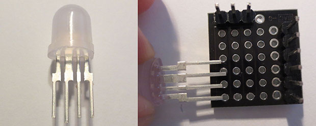
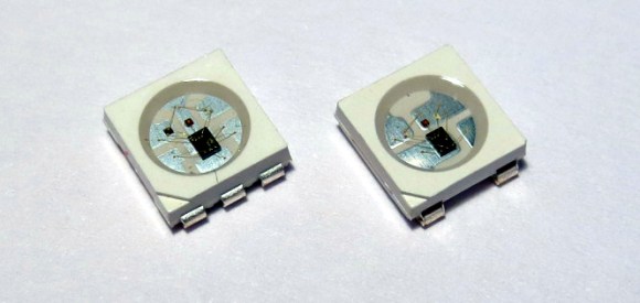
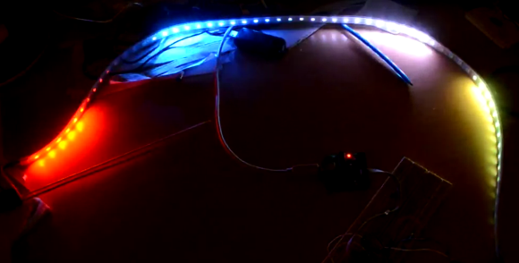
For how often the Raspberry Pi is used as a media server, and how easy it is to connect a bunch of LEDs to the GPIO pins on the Pi, we’re surprised we haven’t seen something like Hyperion before. It uses the extremely common WS2812b individually controllable RGB LEDs to surround the wall behind your TV with the colors on the edges of the screen.

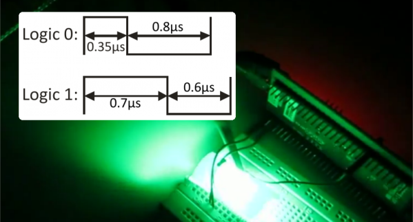
One of the big features of Hyperion is the huge number of LEDs it’s able to control; a 50 LED strip only eats up about 1.5% of the Pi’s CPU. It does this with a “Mini UART” implemented on the Pi running at 2MHz.

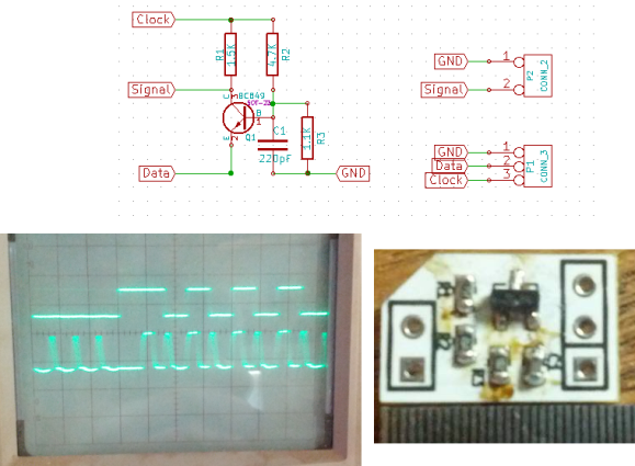
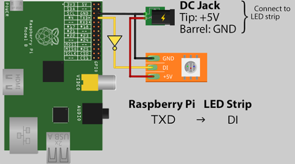
There’s only one additional component needed to run a gigantic strip of RGB LEDs with a Pi – an inverter of some sort made with an HCT-series logic chip. After that, you’ll only need to connect the power and enjoy a blinding display behind your TV or monitor.

Thanks [emuboy] for sending this one in.


Fail Of The Week: WS2811 Pixel Failure On FLED

This Fail of the Week project comes from one of Hackaday’s own. [Ben] took on the FLED data visualization project as a way to make the SupplyFrame decor a lot more fun. He had quite a bit of help soldering the 96 WS2811 pixels into their custom made 6’x4′ enclosure and the results are really awesome. In addition to showing server load and playing games, FLED has become something of a job interview. Sit the prospective employee down at a terminal and give them an hour to code the most interesting visualization they are capable of.

But two weeks ago [Ben] staggered into the office and found the display was dead. Did he try turning it off and back on again? Yes, but to no avail. The power supply wasn’t the issue and there was no option but to pull the display off the wall and crack it open for a look at all those pixels. Since every one of them had 4 solder joints on either side he figured the problem was with a broken connection. But not so. He resorted to a binary search for the offending pixel by  cutting the strand in half, and testing each portion. He tracked it down to the pixel whose underside was blackened as you can see above.

[Ben] thinks one of the capacitors inside the sealed enclosure blew, but isn’t certain. Feel free to tell us what you think failed in this component. But the thing we’d really like to know is if there is a more clever way to sniff out the offensive pixel without cutting the connections? Four hours on the floor with this thing (and no knee-pads) and [Ben] has sworn off sourcing pixels from random Chinese suppliers. He might go with pre-assembled strings next time. We chuckle; this is the high-tech equivalent of trying to get old strands of Christmas lights to work.

If you haven’t seen FLED in action, check it out after the break. It amazing how LED intensity and quality diffuser material can make a perfect grid of LEDs seem to dance in waves and color curves.

Continue reading “Fail Of The Week: WS2811 Pixel Failure On FLED”

Breadboardable WS2812 LEDs

LED

Hackaday sees a ton of projects featuring the WS2812 series of digitally controllable RGB LEDs, in the form of bare chips, RGB LED strips, or some form of Adafruit’s NeoPixels. All these WS2812 LED products have one thing in common – they’re chip LEDs, making some projects difficult to realize. Now there’s a new member of the WS2812 family – a through-hole LED version – that should be available through the usual sources sometime later this year.

The key difference between these and the usual WS2812 LEDs is the packaging; these are 8mm LEDs with pins for power, ground, data in, and data out. With the preexisting libraries, this 8mm LED should work just the same as any other WS2812 LED.

Aside from a through-hole package, these new LEDs are very diffuse and aren’t as blinding as the normal chip LEDs. If you want to pick up a few of these LEDs, they’re available here, 13 LEDs for $15. There’s a lot of potential here for RGB LED cubes, something we hope to see sooner rather than later.

WS2811 SPI Driver Using One Transistor And Passives

ws2811-spi-driver

We love the WS28xx projects because even if we never plan to use them, the signal timing is like the most addictive puzzle game ever. For instance, check out this WS2811A driver which uses hardware SPI to generate the signals.

The WS28xx offerings place a microcontroller inside an RGB LED, allowing them to be individually addressed in very long chains or large matrices (still a chain but different layout). But the timing scheme used to address them doesn’t play well with traditionally available microcontroller peripherals. [Brett] had been intrigued by some of the attempts to bend hardware SPI to the will of the WS2811 — notably [Cunning_Fellow’s] work featured in this post. He took it a great step forward by simplifying the driver to just one transistor, three resistors, and a capacitor.

Click through the link above for his step-by-step description of how the circuit works (it’s not worth re-explaining here as he does a very concise job himself). The oscilloscope above shows the SPI signal on top and the resulting timing signal below. You will notice the edges aren’t very clean, which requires the first pixel to be very close to the driver or risk further degradation. But, since the WS28xx drivers feature a repeater which cleans up signals like this, it’s smooth sailing after the first pixel.


Rewriting WS2812 Driver Libraries For Optimization

ws2812_compared

We like [Tim’s] drive for improvement. He wrote a WS2812 driver library that works with AVR and ARM Cortex-M0 microcontrollers, but he wasn’t satisfied with how much of the controller’s resources the library used to simply output the required timing signal for these LED modules. When he set out to build version 2.0, he dug much deeper than just optimizing his own code.

We remember [Tim] from his project reverse engineering a candle flicker LED. This time, he’s done more reverse engineering by comparing the actual timing performance of the WS2812(B) module with its published specs. He learned that although several timing aspects require precision, others can be fudged a little bit. To figure out which ones, [Tim] used an ATtiny85 as a signal-generator and monitored performance results with a Saleae logic analyzer. Of course, to even talk about these advances you need to know something about the timing scheme, so [Tim] provides a quick run-through of the protocol as part of his write-up.

Click the top link to read his findings and how he used them to write the new library, which is stored in his GitHub repository.

Using DMA To Drive WS2812 LED Pixels

It’s pretty well known by now that the LED pixel hardware which is starting to be commonplace, both WS2811 and WS2812, needs pretty strict timing in order to address them. There are libraries out there which mean almost no work on your part, but that’s no fun. [Elia] started looking into what it takes to drive the hardware, trying out a few 8-bit micros before moving to 32-bit with the help of an STM32VL Discovery Board. The move to a beefier processor brings a lot of speed, but why bit bang everything? He came up with a way to use the PWM and DMA features of the chip to drive the LEDs.

DMA is the Direct Memory Access unit that allows you to change the values being sent to the pixel without interrupting the processor. This is done by pre-loading the data at a memory location. This buffer is automatically read by the DMA unit — its values are used to set the PWM timer compare trigger in order to send out logic values show in the diagram above.

If you do want to delve further into this topic here’s a collection of techniques for driving the WS2811.

Continue reading “Using DMA To Drive WS2812 LED Pixels”

WS2811 Can Be Addressed At 800kHz Using A 8MHz Clock

ws2811-running-at-8mhz

Timing is everything and that’s why most communication protocols require a very accurate clock source. The WS2811 LED strip controllers are no different. But [Danny] figured out a way to drive them reliably with an 8MHz clock source.

The WS2811 has become one of the most popular controllers for RGB pixels and strips alike. We’ve seen several hacks used to address them, including the 16MHz AVR technique that inspired [Danny] to take on this project. He planned to use that library but the 25-day shipping time for a 16MHz crystal drove home to invent a way to use the internal oscillator instead.

The gist of the hack is that he wrote assembly code to handle pairs of binary bit values. With a code block for each of the four possible combinations in hand he had to find a way to craft the conditional jumps to preserve accurate timing. After hitting the wall trying to solve this puzzle by hand he wrote a C++ program to solve it for home. The proof is in this video which shows one chip driving multiple Larson scanners on a single strip.

Continue reading “WS2811 Can Be Addressed At 800kHz Using A 8MHz Clock”