Using WS2811 Chip To Drive Incandescent Lamps

What makes the WS2812-style individually addressable pixel LEDs so inviting? Their rich colors? Nope, you can get RGB LEDs anywhere. Their form factor? Nope. Even surface-mount RGBs are plentiful and cheap. The answer: it’s the integrated controller. It’s just so handy to speak an SPI-like protocol to your LEDs — it separates the power supply from the data, and you can chain them to your heart’s desire. Combine this controller and the LEDs together in a single package and you’ve got a runaway product success.

But before the WS2812, there was the WS2811 — a standalone RGB controller IC. With the WS2812s on the market, nobody wants the lowly WS2811’s anymore. Nobody except [Michael Krumpus], that is. You see, he likes the old-school glow of incandescent, but likes the way the WS2812 strings are easy to drive and extend. So he bought a bag of WS2811s and put the two together.

The controller IC can’t handle the current that an incandescent bulb requires, so he added a MOSFET to do the heavy lifting. After linking a few of these units together, he discovered (as one does with the LED-based WS2812s eventually) that the switching transients can pull down the power lines, so there is a beefy capacitor accompanying each bulb.

He wanted each bulb to be independently addressable, so he only used the blue line of the RGB controller, which leaves two outputs empty. I’m sure you can figure out something to do with them.

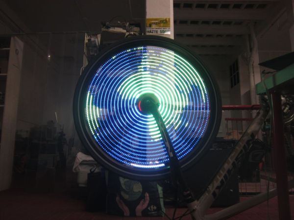
Needless to say, we’ve seen a lot of WS2812 hacks here. It’s hard to pick a favorite. [Mike] of “mike’s electric stuff” fame built what may be the largest installation we’ve seen, and this hack that effectively projection-maps onto a randomly placed string of WS2812s is pretty cool. But honestly, no project that blinks or glows can go far wrong, right?

Continue reading “Using WS2811 Chip To Drive Incandescent Lamps”

Driving WS2811 LEDs With…VGA?

We thought we’d seen it all. All the ways to drive WS2811/2812 “Neopixel” LEDs, that is. And then [Steve Hardy] comes up with a new one: hacking a computer’s VGA output to drive 500 WS2811s in a string. And it’s quite a hack. You can check out the video (it’s worth enduring the horrible wind noise) below the break.

bits[Steve]’s big realization was that he could send the digital data that the Neopixels needed by carefully selecting a resolution and clock rate for the VGA to match the timings that the WS2811 modules wanted. A resolution of 840×1000 at 28MHz produces 70 pixels per WS2811 bit, or 12 bits per line. This means two VGA lines need to be sent for the RGB triple for each LED, hence the 1000 rows.

There are some further tricks before [Steve] got around to writing a custom OpenGL shader that converts regular graphics to his strange black-and-white bit pattern to drive the LEDs, but you’re going to have to read [Steve’s] blog for all that. If you’re waiting for a full code write-up, [Steve] says that one’s pending.

We’re just stoked to see the computing power that lies within a video card used for other purposes. Once you think of the VGA output as a general-purpose high speed (analog!) output, it opens up a whole bunch of possibilities if you can write the corresponding video software. As [Steve] points out, he’s only using the red channel right now — he could trivially add another 1000 LEDs just by tweaking his video code.

Continue reading “Driving WS2811 LEDs With…VGA?”

An RGB Word Clock, Courtesy Of WS2812s

A word clock – a clock that tells the time with illuminated letters, and not numbers – has become standard DIY electronics fare; if you have a soldering iron, it’s just what you should build. For [Chris]’ word clock build, he decided to build an RGB word clock.

A lot has changed since the great wordclock tsunami a few years back. Back then, we didn’t have a whole lot of ARM dev boards, and everyone’s grandmother wasn’t using WS2812 RGB LED strips to outshine the sun. [Chris] is making the best of what’s available to him and using a Teensy 3.1, the incredible OctoWS2812 library and DMA to drive a few dozen LEDs tucked behind a laser cut stencil of words.

The result is blinding, but the circuit is simple – just a level shifter and a big enough power supply to drive the LEDs. The mechanical portion of the build is a little trickier, with light inevitably leaking out of the enclosure and a few sheets of paper working just enough to diffuse the light. Still, it’s a great project and a great way to revisit a classic project.

The Most Minimal WS2812B Driver

Whether you call them individually controllable RGB LEDs, WS2812, or NeoPixels, there’s no denying they are extremely popular and a staple of every glowey and blinkey project. Fresh off the reel, they’re nearly useless – you need a controller, and that has led to many people coming up with many different solutions to the same problem. Here’s another solution, notable because it’s the most minimal WS2812 driver we’ve ever seen.

The critical component in this build is NXP’s LPC810, an ARM Cortex M0+ in an 8-pin DIP package. Yes, it’s the only ARM in a DIP-8, but still able to run at 30MHz, and hold a 4kB program.

JeeLabs is using the SPI bus on the LPC810 to clock out data at the rate required by the LEDs. The only hardware required is a small LED to drop the voltage from 5V to 3.3V and a decoupling capacitor. Yes, you could easily get away with this as a one-component build.

The build consists of a ring of sixty WS2812b RGB LEDs, and the chip dutifully clocking out bits at the correct rate. It’s the perfect start to an LED clock project, an Iron Man arc reactor (are we still doing those?), or just random blinkey LEDs stuffed into a wearable.

Thanks [Martyn] for sending this one in.

Measuring The Length Of WS2812 Strips

[Tim] discovered a simple way to measure the length of WS2812 addressable LED strips from a microcontroller. This is great for any project that can have an arbitrary length of addressable LED strip attached to it.

The simplest (and perhaps most reliable) way to measure strip length is by feeding the serial output pin of the end of the strip back to the microcontroller. The microcontroller keeps clocking bits into the strip until it receives data from the end of the strip. [Tim] didn’t want to run an additional signal to the end of his strip, so he found another solution.

[Tim] used the ADC of his microcontroller (an ATtiny) to measure supply voltage droop as LEDs are turned on. Each LED draws around 60mA at full brightness, so [Tim] sequentially turned on each LED and watched the ADC for slight voltage changes. If the voltage changed, there must be an LED at that address. [Tim] does note that this method is extremely dependent on the power supply used and only works on short strips. Check out his blog post for more details.

Bike Persistance of Vision

Simple POV Bike Effects With WS2811 Strips

[Andrew] wrote in with a new take on the classic persistence of vision bike spoke hack. While many of these POV setups use custom PCBs and discrete LEDs, [Andrew]’s design uses readily available off-the-shelf components: WS2811 LED strips, an Arduino, an Invensense IMU breakout board, and some small LiPo batteries.

[Andrew] also implemented a clever method of controlling his lights. His code detects when the rider taps the brakes in certain patterns, which allows changing between different light patterns. He does note that this method isn’t incredibly reliable due to some issues with his IMU, so now he senses when the rider taps on the handlebars as well.

If you want to build your own bike POV setup, you’re in luck. [Andrew] wrote up detailed instructions that outline the entire build process. He also provides links to sources for each part to make building your own setup even easier. His design is pretty affordable too, coming in at just under $50 per wheel. Check out a video of [Andrew]’s setup in action after the break.

Continue reading “Simple POV Bike Effects With WS2811 Strips”

WS2812 at 670 kHz

Driving WS2812B Pixels, With DMA Based SPI

Typically bit-banging an I/O line is the common method of driving the WS2812B (WS2811) RGB LEDs. However, this ties up precious microcontroller cycles while it waits around to flip a bit. A less processor intensive method is to use one of the built-in Serial Peripheral Interface (SPI) modules. This is done using specially crafted data and baud rate settings, that when shifted out over the Serial Data Out (SDO) pin, recreate the needed WS2812B signal timing. Even when running in SPI mode, your hardware TX buffer size will limit how many pixels you can update without CPU intervention.

[Henrik] gets around this limitation by using peripheral DMA (Direct Memory Access) to the SPI module in the Microchip PIC32MX250F128B microcontroller. Once properly configured, the DMA controller will auto increment through the defined section of DMA RAM, sending the pixel data over to the SPI module. Since the DMA controller takes care of the transfer, the micro is free to do other things. This makes all of DMA memory your display buffer. And leaves plenty of precious microcontroller cycles available to calculate what patterns you want the RGB LEDs to display.

Source code is available at the above link for those who would like to peruse, or try it out. This is part of [Henrik’s] Pixel Art Project. Video of DMA based SPI pixels after the break:

Continue reading “Driving WS2812B Pixels, With DMA Based SPI”