A PCB business card that plays tic-tac-toe with red and blue LEDs.

2024 Business Card Challenge: Go Tic-Tac-Toe-to-Toe With Them

There is perhaps no more important time to have a business card than when you’re in college, especially near the end when you’re applying for internships and such. And it’s vital that you stand out from the crowd somehow. To that end, Electrical & Computer Engineer [Ryan Chan] designed a tidy card that plays tic-tac-toe.

Instead of X and O, the players are indicated by blue and red LEDs. Rather than having a button at every position, there is one big control button that gets pressed repeatedly until your LED is in the desired position, and then you press and hold to set it and switch control to the other player. In addition to two-player mode, the recipient of your card can also play alone against the ATMega.

The brains of this operation is an ATMega328P-AU with the Arduino UNO bootloader for ease of programming. Schematic and code are available if you want to make your own, but we suggest implementing some type of changes to make it your own. Speaking of, [Ryan]  has several next steps in mind, including charlieplexing the LEDs, using either USB-C or a coin cell for power, upgrading the AI, and replacing the control button with a capacitive pad or two. Be sure to check it out in action in the two videos after the break.

Continue reading “2024 Business Card Challenge: Go Tic-Tac-Toe-to-Toe With Them”

An Easy Transparent Edge Lit Display

Displays are crucial to modern life; they are literally everywhere. But modern flat-panel LCDs and cheap 7-segment LED displays are, well, a bit boring. When we hackers want to display the progress of time, we want something more interesting, hence the plethora of projects using Nixie tubes and various incantations of edge-lit segmented units. Here is [upir] with their take on the simple edge-lit acrylic 7-segment design, with a great video explanation of all the steps involved.

Engraving the acrylic sheets by hand using 3D printed stencils

The idea behind this concept is not new. Older displays of this type used tiny tungsten filament bulbs and complex light paths to direct light to the front of the display. The modern version, however, uses edge-lit panels with a grid of small LEDs beneath each segment, which are concealed within a casing. This design relies on the principle of total internal reflection, created by the contrast in refractive indices of acrylic and air. Light entering the panel from below at an angle greater than 42 degrees from normal is entirely reflected inside the panel. Fortunately, tiny LEDs have a wide dispersion angle, so if they are positioned close enough to the edge, they can guide sufficient light into the panel. Once this setup is in place, the surface can be etched or engraved using a CNC machine or a laser cutter. A rough surface texture is vital for this process, as it disrupts some of the light paths, scattering and directing some of it sideways to the viewer. Finally, to create your display, design enough parallel-stacked sheets for each segment of the display—seven in this case, but you could add more, such as an eighth for a decimal point.

How you arrange your lighting is up to you, but [upir] uses an off-the-shelf ESP32-S3 addressable LED array. This design has a few shortcomings, but it is a great start—if a little overkill for a single digit! Using some straightforward Arduino code, one display row is set to white to guide light into a single-segment sheet. To form a complete digital, you illuminate the appropriate combination of sheets. To engrave the sheets, [upir] wanted to use a laser cutter but was put off by the cost. A CNC 3018 was considered, but the choice was bewildering, so they just went with a hand-engraving pick, using a couple of 3D printed stencils as a guide. A sheet holder and light masking arrangement were created in Fusion 360, which was extended into a box to enclose the LED array, which could then be 3D printed.

If you fancy an edge-lit clock (you know you do) check out this one. If wearables are more your thing, there’s also this one. Finally, etched acrylic isn’t anywhere near as good as glass, so if you’ve got a vinyl cutter to hand, this simple method is an option.

Continue reading “An Easy Transparent Edge Lit Display”

Build Your Own Core Rope Memory Module?

[Luizão] wanted to create some hardware to honour the memory of the technology used to put man on the moon and chose the literal core of the project, that of the hardware used to store the software that provided the guidance. We’re talking about the magnetic core rope memory used in the Colossus and Luminary guidance computers. [Luizão] didn’t go totally all out and make a direct copy but instead produced a scaled-down but supersized demo board with just eight cores, each with twelve addressable lines, producing a memory with 96 bits.

The components chosen are all big honking through-hole parts, reminiscent of those available at the time, nicely laid out in an educational context. You could easily show someone how to re-code the memory with only a screwdriver to hand; no microscope is required for this memory. The board was designed in EasyEDA, and is about as simple as possible. Being an AC system, this operates in a continuous wave fashion rather than a pulsed operation mode, as a practical memory would. A clock input drives a large buffer transistor, which pushes current through one of the address wires via a 12-way rotary switch. The cores then act as transformers. If the address wire passes through the core, the signal is passed to the secondary coil, which feeds a simple rectifying amplifier and lights the corresponding LED. Eight such circuits operate in parallel, one per bit. Extending this would be easy.

Continue reading “Build Your Own Core Rope Memory Module?”

Inside NFC

[Ken Shirriff] likes to take chips apart and this time his target is an NFC chip used in Montreal transit system tickets. As you might expect, the tickets are tiny, cheap, and don’t have any batteries. So how does it work?

The chip itself is tiny at 570 µm × 485 µm. [Ken] compares it to a grain of salt. The ticket has a thin plastic core with a comparatively giant antenna onboard.

Continue reading “Inside NFC”

The Book That Could Have Killed Me

It is funny how sometimes things you think are bad turn out to be good in retrospect. Like many of us, when I was a kid, I was fascinated by science of all kinds. As I got older, I focused a bit more, but that would come later. Living in a small town, there weren’t many recent science and technology books, so you tended to read through the same ones over and over. One day, my library got a copy of the relatively recent book “The Amateur Scientist,” which was a collection of [C. L. Stong’s] Scientific American columns of the same name. [Stong] was an electrical engineer with wide interests, and those columns were amazing. The book only had a snapshot of projects, but they were awesome. The magazine, of course, had even more projects, most of which were outside my budget and even more of them outside my skill set at the time.

If you clicked on the links, you probably went down a very deep rabbit hole, so… welcome back. The book was published in 1960, but the projects were mostly from the 1950s. The 57 projects ranged from building a telescope — the original topic of the column before [Stong] took it over — to using a bathtub to study aerodynamics of model airplanes.

X-Rays

[Harry’s] first radiograph. Not bad!
However, there were two projects that fascinated me and — lucky for me — I never got even close to completing. One was for building an X-ray machine. An amateur named [Harry Simmons] had described his setup complaining that in 23 years he’d never met anyone else who had X-rays as a hobby. Oddly, in those days, it wasn’t a problem that the magazine published his home address.

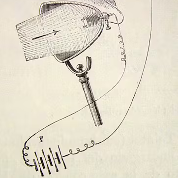
You needed a few items. An Oudin coil, sort of like a Tesla coil in an autotransformer configuration, generated the necessary high voltage. In fact, it was the Ouidn coil that started the whole thing. [Harry] was using it to power a UV light to test minerals for flourescence. Out of idle curiosity, he replaced the UV bulb with an 01 radio tube. These old tubes had a magnesium coating — a getter — that absorbs stray gas left inside the tube.

Continue reading “The Book That Could Have Killed Me”

Testing Large Language Models For Circuit Board Design Aid

Beyond bothering large language models (LLMs) with funny questions, there’s the general idea that they can act as supporting tools. Theoretically they should be able to assist with parsing and summarizing documents, while answering questions about e.g. electronic design. To test this assumption, [Duncan Haldane] employed three of the more highly praised LLMs to assist with circuit board design. These LLMs were GPT-4o (OpenAI), Claude 3 Opus (Anthropic) and Gemini 1.5 (Google).

The tasks ranged from ‘stupid questions’, like asking the delay per unit length of a trace on a PCB, to finding parts for a design, to designing an entire circuit. Of these tasks, only the ‘parsing datasheets’ task could be considered to be successful. This involved uploading the datasheet for a component (nRF5340) and asking the LLM to make a symbol and footprint, in this case for the text-centric JITX format but KiCad/Altium should be possible too. This did require a few passes, as there were glitches and omissions in the generated footprint.

When it came to picking components for a design, it’s clear that you’re out of luck here unless you’re trying to create a design that a million others have made before you in exactly the same way. This problem got worse when trying to design a circuit and ultimately spit out a netlist, with the best LLM (Claude 3 Opus) giving nonsensical suggestions for filter designs and mucking up even basic amplifier designs, including by sticking decoupling capacitors and random resistors just about everywhere.

Effectively, as a text searching tool it would seem that LLMs can have some use for engineers who are tired of digging through yet another few hundred pages of poorly formatted and non-indexed PDF datasheets, but you still need to be on your toes with every step of the way, as the output from the LLM will all too often be slightly to hilariously wrong.

ESP32 Brings New Features To Classic Geiger Circuit

There’s no shortage of Geiger counter projects based on the old Soviet SBM-20 tube, it’s a classic circuit that’s easy enough even for a beginner to implement — so long as they don’t get bitten by the 400 volts going into the tube, that is. Toss in a microcontroller, and not only does that circuit get even easier to put together and tweak, but now the features and capabilities of the device are only limited by how much code you want to write.

Luckily for us, [Omar Khorshid] isn’t afraid of wrangling some 0s and 1s, and the result is the OpenRad project. In terms of hardware, it’s the standard SBM-20 circuit augmented with a LILYGO ESP32 development board that includes a TFT display. But where this one really shines is the firmware.

With the addition of a few hardware buttons, [Omar] was able to put together a very capable interface that runs locally on the device itself. In addition, the ESP32 serves up a web page that provides some impressive real-time data visualizations. It will even publish its data via MQTT if you want to plug it into your home automation system or other platform.

Between the project’s Hackaday.io page and GitHub repository, [Omar] has done a fantastic job of documenting the project so that others can recreate it. That includes providing the schematics, KiCad files, and Gerbers necessary to not only get the boards produced and assembled, but modified should you want to adapt the base OpenRad design.

This project reminds us of the uRADMonitor, which [Radu Motisan] first introduced in 2014 to bring radiation measuring to the masses. This sort of hardware has become far more accessible over the last decade, bringing the dream of a globally distributed citizen-operated network of radiation and environmental monitors much closer to reality.

Continue reading “ESP32 Brings New Features To Classic Geiger Circuit”