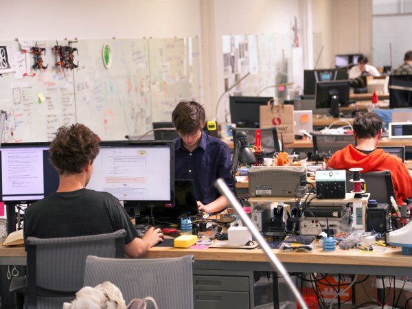
I was visiting San Francisco, scratching my head for something cool to cover for Hackaday. When it hit me: this is one of the leading cities in the world for starting new companies. It’s known for its software, but with Tesla, Type A Machines, Intel, Apple, and more within an hour’s drive of the city, there’s got to be a hardware scene as well. Silicon isn’t a software product after-all. But where do you find it, and how do you get a hardware start-up going in one of the most expensive cities in the world?
That’s where hardware accelerators or incubators, whichever name they prefer, come in. One-third hackerspace, two-thirds business crash course, they help you skip a lot of the growing pains associated with starting a capital intensive thing like a hardware business. I dropped in, and they kindly gave me a few minutes of their time. I wanted to find out what a hacker could do if they felt it was time to turn those skulls into dollars. What are the requirements. What is the cost? What help does the incubator offer to the burgeoning capitalist in a hacker?
Continue reading “When You Get Serious About Selling A Project, Consider An Accelerator”
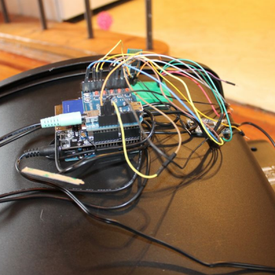 The build itself is uncomplicated and can be replicated with ease. A servo motor helps flip the lid open and close. This is triggered by an ultrasonic ping sensor, which responds when someone waves a hand in front of the trash can. A second ping sensor helps inform the user when it is full and needs to be emptied. A Leonardo with the