This was both an amusing and frightening talk. [Sam Bowne] presented How to Trojan Financial Android Apps on Saturday afternoon at the LayerOne Conference. [Sam] calculates that 80-90% of the apps provided by major financial institutions like banks and investment companies are vulnerable and the ease with which trojans can be rolled into them is incredible.
Some Background
[Sam] did a great job of concisely describing the circumstances that make Android particularly vulnerable to the attacks which are the subject of the talk. Android programs are packaged as APK files which are easy to unpack. The “compiled” code itself is called smali and is readable in a similar way as Java. It’s super easy to unpack and search this byte code using grep. Once the interesting parts are located, the smali code can be altered and the entire thing can be repackaged. The app will need to be resigned but Google doesn’t control the signing keys so an attacker can simply generate a new key and use that to sign the app. The user still needs to install the file, but Android allows app installation from webpages, email, etc. so this isn’t a problem for the bad guys either.
The Attack
So what can be done? This is about information harvesting. [Sam’s] proof of concept uses a python script to insert logging for every local variable. The script looks at the start of every module in the smali code, grabs the number of local variables, increments it by one and uses this extra variable to write out the values through logcat.
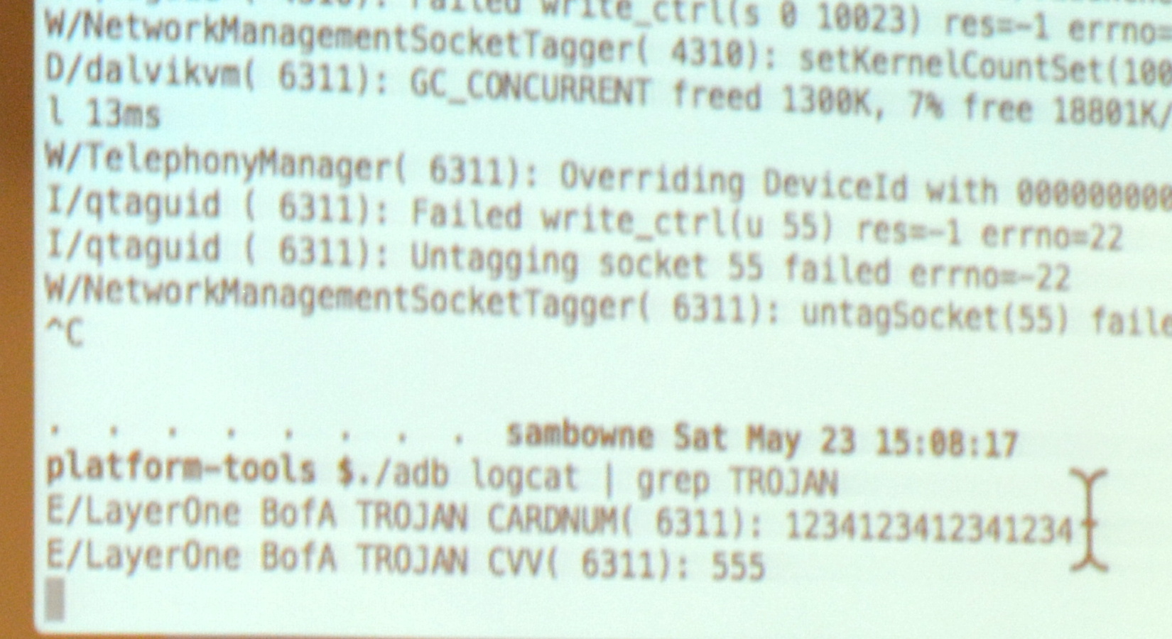
He demonstrated live on the Bank of America app. From the user side of things it looks exactly like the official app, because it is the official app. However, when you register your account the log reports the card number as you can see here. Obviously this information could easily be phoned-home using a number of techniques.
As mentioned, the vast majority of banking and financial apps are vulnerable to this, but some have made an attempt to make it more difficult. He found the Bancorp app never exposes this information in local variables so it can’t just be logged out. However, the same trojan technique works as a keylogger since he found the same function kept getting called every time a key is pressed. The same was true of the Capital One app, but it echos out Google’s Android keymap values rather than ascii; easy enough to translate back into readable data though.
The Inability to Report Vulnerabilities
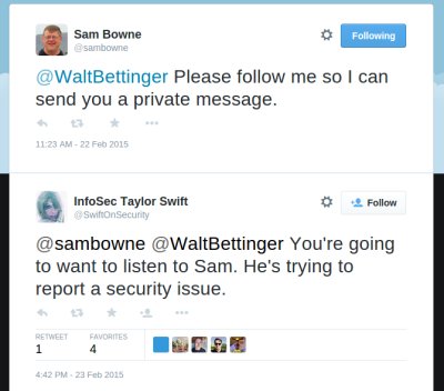 What is the most troubling is that none of these companies have a means of reporting security vulnerabilities. It was amusing to hear [Sam] recount his struggle to report these issues to Charles Schwab. Online contact forms were broken and wouldn’t post data and several publicly posted email addresses bounced email. When he finally got one to accept the email he later discovered another user reporting on a forum that nobody ever answers back on any of the Schwab accounts. He resorted to a trick he has used many times in the past… Tweeting to the CEO of Charles Schwab to start up a direct-message conversation. This itself is a security problem as @SwiftOnSecurity proves by pointing out that whenever @SamBowne Tweets a CEO it’s because he found a vulnerability in that company’s platform and can’t find a reasonable way to contact the company.
There is Hope
Although very rare, sometimes these apps do get patched. The Trade King app was updated after his report and when [Sam] tried the exploit again it crashes at start-up. The log reports a verification failure. This indicates that the injected code is being noticed, but [Sam] wonders if the verification is included in the app itself. If it is, then it will be possible to track it down and disable it.
This may sound like all of us Android users should despair but that’s not the case. Adding verification, even if it’s possible to defeat it, does make the apps safer; attackers may not want to invest the extra time to try to defeat it. Also, there are obsfucators available for a few thousand dollars that will make these attacks much more difficult by making variable names unreadable. The free obsfucator available now with the Android development suites doesn’t change names of everything… local variables are left unaltered and programmers have a habit of using descriptive names for variables. For instance, BofA used “CARDNUM” in the example above.
The Slides
[Sam Bowne’s] slides and testing results for the entire talk are available under the “Upcoming Events” part of his website.

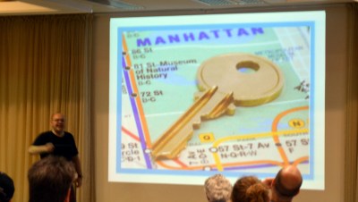 A master key for the NYC Subway was compromised and available for sale.
 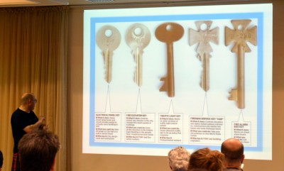 Worse, was the availability of fire-department
  [Jos’] example of doing the right thing is to use a “prop” key for news stories. Here he is posing with a key after the talk. Unfortunately this is my own house key, but I’m the one taking pictures and I have blurred the teeth for my own security. However, I was shocked during image editing at the quality of the outline in the image — taken at 6000×4000 with no intent to make something that would serve as a source for a copy. It still came out remarkably clear.


