Just when you thought you’d seen an Arduino do everything, [birdyberth] built an Arduino powered Electrocardiogram (ECG or EKG). Electrocardiography is a non invasive method of studying the heart. For many of us that means a 10 minute test during our yearly physical exam. Medical grade ECGs can use up to 10 electrodes. To keep things simple [birdyberth] went the route of a few circuits we’ve seen before, and reduced it to two electrodes and a ground reference. [birdyberth] makes note that the circuit is only safe if battery power is used.
The “heart” of any ECG is an instrumentation amplifier. Instrumentation amplifiers can be thought of as super differential amplifiers. They have buffered inputs, low DC offset, low drift, low noise, high open loop gain, and high impedance among other favorable characteristics. The downside is cost. A typical op amp might cost 0.50 USD in single piece quantities. Instrumentation amplifiers, like [birdyberth’s] INA128 can cost $8.30 or (much) more each. The extra cost is understandable when one thinks about the signals being measured. The ECG is “picking up” the heart’s electrical signals from the outside on skin. On commonly used ECG graph paper, a 1mm square translates to about .1 mV. High gain and clean signals are really needed to get any meaningful data here.
Electrodes are another important part of an ECG. Medical grade ECG units typically use disposable adhesive electrodes that make a strong electrical connection to the skin, and hurt like heck when they’re ripped off by the nurse. [birdyberth] was able to make electrodes using nothing more than tin foil and paper clips. We think the real trick is in the shower gel he used to make an electrical connection to his skin. While messy, the gel provides a low resistance path for the tiny currents to flow.
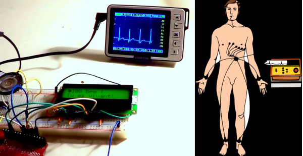
The actual processing in [birdyberth’s] circuit is easy to follow. The signal from the instrumentation amplifier is sent through a low pass filter, through a 741 op amp, and then on to the Arduino. The Arduino uses a 16×2 LCD to display heart rate in beats per minute, along with a friendly message informing you if you are alive or dead. The circuit even provides audible feedback for heart beats, and the classic “flatline tone” when the users either disconnects the electrodes or expires. [birdyberth] has also plugged in his pocket oscilloscope just after the low pass filter. As his video shows, the familiar ECG waveform is clearly visible. We’d love to see a more complex version of this hack combined with [Addie’s] heart simulator, so we could know exactly which heart malady is killing us in real time!
Continue reading “Arduino Powered ECG Informs Users Of Their Death” →