[ivorjawa] is putting on a haunted house this Halloween that we really don’t want to go to. His robot tentacle is already supremely creepy, and we’re assuming it will only be more frightening once it’s covered in fabric and foam rubber.
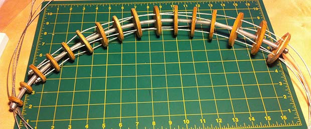
Each tentacle can move on two axes thanks to four steel cables running through this strange Geiger-esque contraption. In the base of the tentacle are two stepper-motor driven cylinders that take up slack on one cable and draw out another cable. Two of these control boxes, driven by a stepper motor and an Arduino motor shield, allow the tentacle to reach out and grab in any direction. You can check out the mechanics of the build on [ivorjava]’s flickr
On a semi-related note, even though we’re more than a month out from Halloween, we should have more Halloween builds in our tip line by now. If you’re working on one, don’t be afraid to send it in, even if you’re just showing off a work in progress.
Continue reading “Robotic Tentacles For A Disturbing Haunted House”