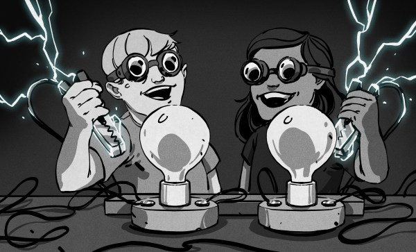
[Boz] wants to build a retrocomputer, but where to start? You could start with the computery bits, like say the CPU or the bus architecture, but where’s the fun in that? Instead, [Boz] built a righteous blinkenlights array.
What’s cool about this display is that it’s ready to go out of the box. All of the LEDs are reverse-mount and assembled by the board maker. The 19″ 2U PCBs serve as the front plates, so [Boz] was careful not to use any through-hole parts, which also simplified the PCB assembly, of course. Each slice has its own microcontroller and a few shift registers to get the bits lit up, and that’s all there is to it. They take incoming data at 9600 baud and output blinkiness.
Right now it pulls out its bytes from his NAS. We’re not sure which bytes, and we think we see some counters in there. Anyway, it doesn’t matter because it’s so pretty. And maybe someday the prettiness will lure [Boz] into building a retrocomputer to go under it. But honestly, we’d just relax and watch the blinking lights.
Hackaday was at Chaos Communication Congress last week, and it’s one of those big hacker events that leaves you with so much to think about that I’m still processing it. Just for scope, the 38th CCC is a hacker event with about 15,000 attendees from all around Europe, and many from even further. If I were to characterize the crowd on a hardware-software affinity scale, I would say that it skews heavily toward the software side of the hacker spectrum.
What never ceases to amaze me is that there are a couple of zones that are centered on simple beginner soldering and other PCB art projects that are completely full 20 hours of the day. I always makes me wonder how it is possible to have this many hackers who haven’t picked up a soldering iron. Where do all these first-timers come from? I think I’m in a Hackaday bubble where not only does everyone solder at least three times a day, some of us do it with home-made reflow ovens or expensive microscopes.
But what this also means is that there’s tremendous reach for interesting, inviting, and otherwise cool beginner hardware projects. Hands-on learning is incredibly addictive, and the audience for beginner projects is probably ten times larger than that for intermediate or advanced builds. Having watched my own son putting together one of these kits, I understand the impact they can have personally, but it’s worth noting that the guy next to him was certainly in his mid-30s, and the girl across the way was even a few years younger than my son.
So let’s see some cool beginner projects! We’d love to feature more projects that could lure future hackers to the solder-smoky side.
This article is part of the Hackaday.com newsletter, delivered every seven days for each of the last 200+ weeks. It also includes our favorite articles from the last seven days that you can see on the web version of the newsletter.
Want this type of article to hit your inbox every Friday morning? You should sign up!
Adding threads to your 3D prints is a life-changing feature, but obviously there are a lot of trade-offs and considerations when deciding on how to go about this exactly. Between self-tapping screws, printed threads, heat inserts and a dozen other options it can be tough to decide what to go with. In a recent video [Thomas Sanladerer] runs through a few of these options, including some less common ones, and what he personally thinks of them.
Confounding factors are also whether you’re printing on an FDM or resin printer, what size thread you’re targeting and how often the screw or bolt will be removed. The metal heat inserts are generally a good option for durability, but when you have big bolts you get a few other metal-based options too, including thread repair inserts and prong nuts. Tapping threads into a print can also be an option, but takes a fair bit of patience.
Slotted nuts can be an idea if you don’t mind carving a space into your model, and the comments dove on embedding nuts in the print by pausing during printing. Ultimately [Thomas] really likes to use a type of self-forming threads with just three protruding sections into the hole that the bolt taps into, which reduces the stress on the part and works well enough for parts that only have to be screwed down once or twice.
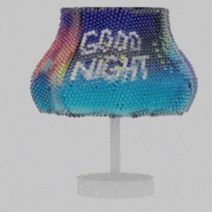
A research project shows that it’s possible to create complex single-piece lenticular objects, or objects that have lenticular lenses built directly into them. The result is a thing whose appearance depends on the viewer’s viewpoint. The object in the image above, for example, is the same object from five different angles.
What’s really neat is that these colorful things have been 3D printed as single objects, no separate lenses or assembly required. Sure, it requires equipment that not just everyone has on their workbench, but we think a clever hacker could put the underlying principles to work all the same.
This lampshade (which was 3D printed as a single object) changes color and displays Good Day or Good Night depending on viewing angle.
The effect is essentially the same as what is sometimes seen in children’s toys and novelties — where a perceived image changes depending on the viewing angle. This principle has been used with a lenticular lens sheet to create a clever lenticular clock, but there’s no need to be limited by what lenses are available off the shelf. We’ve seen a custom 3D printed lenticular lens slapped onto a mobile device to create a 3D screen effect.
Coming back to the research, the objects researchers created go beyond what we’ve seen before in two important ways. First is in using software to aid in designing the object and it’s viewpoints (the plugin for Rhino 3D is available on GitHub), and the second is the scale of the effect. Each lens can be thought of as a pixel whose color depends on the viewing angle, and by 3D printing the lenses, one can fit quite a lot of them onto a surface with a high degree of accuracy.
To make these objects researchers used PolyJet 3D printing, which is essentially UV-cured resin combined with inkjet technology, and can create multi-color objects in a single pass. The lenses are printed clear with a gloss finish, the colors are embedded, and a final hit of sprayed varnish helps with light transmission. It sure beats placing hundreds of little lenses by hand.
Doing the rounds this week is a new operating system for ESP32 microcontrollers, it’s called Tactility, and it comes from [Ken Van Hoeylandt]. It provides a basic operating system level with the ability to run apps from an SD card, and it has the choice of a headless version or an LVGL-based touch UI.
Supported devices so far are some Lillygo and M5Stack boards, with intriguingly, support in the works for the Cheap Yellow Display board that’s caught some attention recently. The term “ESP32” is now a wide one encompassing Tensilica and RISC-V cores and a range of capabilities, so time will tell how flexible it is for all branches of the family.
We find this OS to be interesting, both in its own right and because it joins at least two others trying to do the same thing. There’s [Sprite_TM]’s PocketSprite mini console, and the operating system used by the series of Netherlands hacker camp badges, We’ll be trying to get a device running it, in order to give you a look at whether it’s suitable for your projects. If it runs well on the cheaper hardware, it could be a winner!
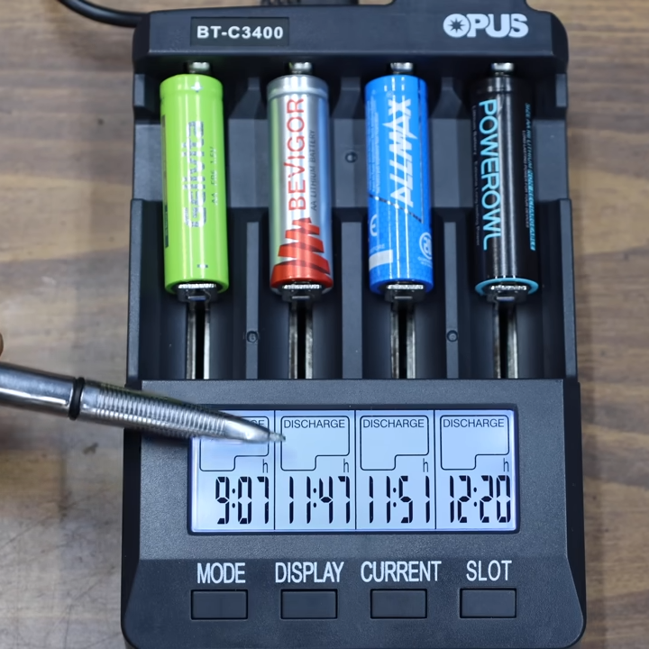
[Project Farm] has a video in which a wide variety of AA cells are analyzed and compared in terms of capacity, internal resistance, ability to deliver voltage under load, and ability to perform in sub-freezing temperatures. Alkaline, lithium, and even some mature rechargeable cells with a couple thousand cycles under their belt were all compared. There are a few interesting results that will can help you get the most from your money the next time you’re battery shopping.
The video embedded below demonstrates a set of tests that we recommend you check out, but the short version is that more expensive (non-rechargeable) lithium cells outperform their alkaline peers, especially when it comes to overall longevity, ability to perform under high-drain conditions, and low temperatures. Lithium cells also cost more, but they’re the right choice for some applications.
Some brands performed better and others worse, but outside of a couple stinkers most were more or less comparable. Price however, was not.
As for how different brands stack up against one another, many of them are more or less in the same ballpark when it comes to performance. Certainly there are better and worse performers, but outside of a couple of stinkers the rest measure up reasonably well. Another interesting finding was that among rechargeable cells that were all several years (and roughly 2,200 charge-discharge cycles) old, a good number of them still performed like new.
Probably the single most striking difference among the different cells is cost — and we’re not just talking about whether lithium versus alkaline AAs are more cost-effective in the long run. Some brands simply cost twice as much (or more!) than others with comparable performance. If you’re in a hurry, jump to [Project Farm] presenting the final ranked results at 19:45 in.
Relying on brand recognition may save you from buying complete junk, but it’s clearly not the most cost-effective way to go about buying batteries. These findings are similar to an earlier effort at wide-scale battery testing which also determined that factoring in price-per-cell was too significant to ignore.
According to [Joanna Goodrich] in IEEE Spectrum, prior to World War II, soldiers who wanted to find land mines, simply poked at the ground with pointed sticks or bayonets. As you might expect, this wasn’t very safe or reliable. In 1941, a Polish signals officer, [Józef Stanislaw Kosacki], escaped to Britain and created an effective portable mine detector.
[Kosaci] was an electrical engineer trained at the Warsaw University of Technology. He had worked as a manager for the Polish National Telecommunication Institute. In 1937, the government tasked him with developing a machine that could detect unexploded grenades and shells. The machine was never deployed.
When Germany invaded Poland in 1939, [Kosacki] returned to military service (he had done a year of compulsory service earlier). He was captured and kept in a prison camp in Hungary. But he managed to escape in late 1939 and joined the Polish Army Corps in Britain, teaching Morse code to soldiers.