Computed Axial Lithography (CAL) is a lighting-fast form of volumetric 3D printing that holds incredible promise for the future, and [The Action Lab] filmed it in action at a Berkeley team’s booth at the “Open Sauce” convention.
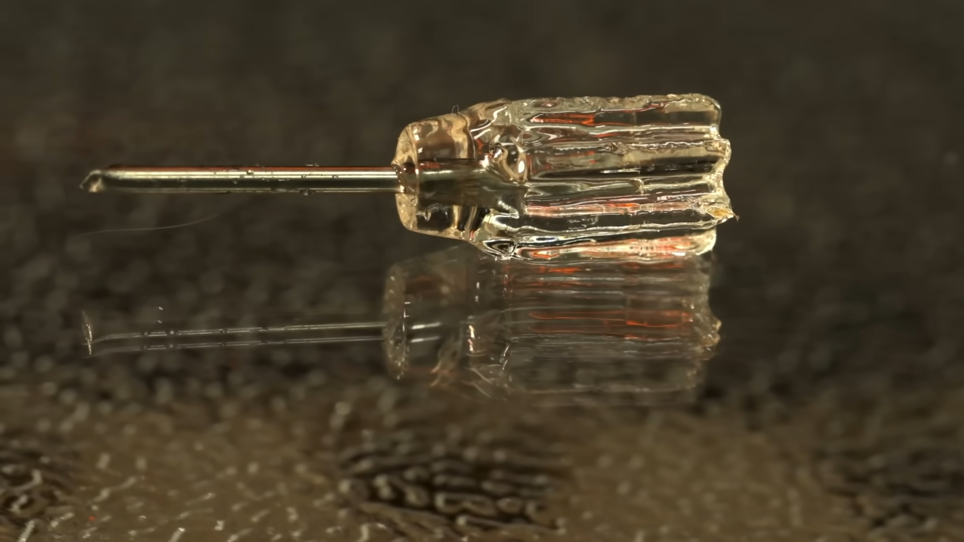
The basic principle works like this: an extra-viscous photopolymer resin sits inside a rotating, transparent cylinder. As the cylinder rotates, UV light is projected into the resin in patterns carefully calculated to reproduce the object being printed. There are no layers, no FEP, and no stop-and-start; it’s just one long exposure from what is effectively an object-generating video, and it does not take long at all. You can probably guess that the photo above shows a Benchy being created, though unfortunately, we’re not told how long it took to produce.
Don’t expect to grab a bottle of SLA resin to get started: not only do you need higher viscosity, but also higher UV transmission than you get from an SLA resin to make this trick work. Like regular resin prints, the resolution can be astounding, and this technique even allows you to embed objects into the print.
It’s not a new idea. Not only have we covered CAL before, we even covered it being tested in zero-G. Floating in viscous resin means the part couldn’t care less about the local gravity field. What’s interesting here is that this hardware is at tabletop scale, and looks very much like something an enterprising hacker might put together.
Indeed, the team at Berkeley have announced their intention to open-source this machine, and are seeking to collaborate with the community on their Discord server. Hopefully we’ll see something more formally “open” in the future, as it’s something we’d love to dig deeper into — and maybe even build for ourselves.
Thanks to [Beowulf Shaeffer] for the tip. If you are doing something interesting with photopolymer ooze (or anything else) don’t hesitate to let us know! Continue reading “CAL 3D Printing Spins Resin Right Round, Baby”