Arduino Ball Throwing Game

arduinogame01_07

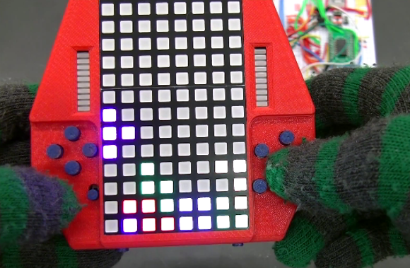
Building your own gaming platform is pretty cool on its own, but when the game actually looks like fun to play, well that’s on a different level of cool. [Zippy314] designed an Arduino based game platform as a Christmas present to his son called the Das Blinken Bonken!

Like all highly addicting games, the gameplay is simple; the player throws a ball at the target board while aiming to hit a specific ‘pad’. As shown in the video after the break, there are many game possibilities with this platform, like trying to hit the illuminated target each time, or just trying to hit all of the pads on the board as fast as possible.

A pad is registered as a ‘hit’ with the help of home-made pressure sensors, which are each constructed in a ‘sandwich’ of pressure-sensitive conductive sheets. This is the same material used in these LED Sneakers. Since the resistance through the sheet lowers as pressure is applied, a simple voltage divider circuit is used to feed the analog inputs on the Arduino, thus making it very easy to detect a ‘hit’. An I2C 4-Digit 7 Segment display keeps score and displays the game title, while a strip of addressable RGB LEDs give player feedback and other vital gameplay information.

Continue reading “Arduino Ball Throwing Game”

Self-Balancing Robots Wobble, But They Don’t Fall Down

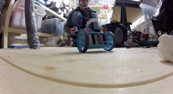
[Trandi] can check ‘build a self-balancing robot’ off of his to-do list. Over a couple of weekends, he built said robot, and, in his own words, managed not to over-design it. It even kept the attention of his 2-year-old son for several minutes, and that’s always a plus.

He was originally going to re-purpose one of his son’s RC cars, but didn’t want to risk breaking it. Instead, he designed a triangular 3-D printed chassis to hold a motor and some cogs to fit both the motor shaft and some re-used Meccano wheels. [Trandi]’s design employs an MPU 6050 6-DOF IMU for the balancing act and is built on an Arduino Nano clone.

[Trandi] is controlling the motor with an L293D, which has built-in flyback diodes to minimize spikes. He found that the Nano clone was not powerful enough to handle everything, so he added an L7805CV voltage regulator. After the break, watch [Trandi]’s cute bot tool around on various types of terrain, with and without a payload.

Don’t have an IMU lying around? You don’t really need one to build a self-balancing bot, as this IR-based lilliputian bot will demonstrate.

Continue reading “Self-Balancing Robots Wobble, But They Don’t Fall Down”

A Transparent 7-Segment Display

Though [Connor] labels it as a work in progress, we’re pretty impressed with how polished his transparent 7-segment display looks. It’s also deceptively simple.

The build uses a stack of seven different acrylic panes, one in front of the other, each with a different segment engraved onto its face. The assembly of panes sits on a small mount which is placed over seven rows of LEDs, with 5 LEDs per row. [Connor] left an air gap between each of the seven individual acrylic panes to clearly distinguish which was lit and to match the separation of the LED rows. To display a number, he simply illuminates the appropriate LED rows, which scatter light across the engraved part without spilling over into another pane.

You can find a brief overview and some schematics on [Connor’s] website, and stick around for the video demonstration below. We’ve featured [Connor’s] work before; if you missed his LCD data transfer hack you should check it out!

Continue reading “A Transparent 7-Segment Display”

Ride, Captain, Ride Aboard Your Arduino-Controlled Autopiloted Sailboat

[Jack], a mechanical engineer, loom builder, and avid sailor wanted an autopilot system for his 1983 Robert Perry Nordic 40 sailboat with more modern capabilities than the one it came with. He knew a PC-based solution would work, but it was a bit out of reach. Once his son showed him an Arduino, though, he was on his way. He sallied forth and built this Arduino-based autopilot system for his sloop, the Wile E. Coyote.

He’s using two Arduino Megas. One is solely for the GPS, and the other controls everything else. [Jack]’s autopilot has three modes. In the one he calls knob steering, a potentiometer drives the existing hydraulic pump, which he controls with a Polulu Qik serial DC motor controller. In compass steering mode, a Pololu IMU locks in the heading to steer (HTS).  GPS mode uses a predetermined waypoint, and sets the course to steer (CTS) to the same bearing as the waypoint.

[Jack]’s system also uses cross track error (XTE) correction to calculate a new HTS when necessary. He has fantastic documentation and several Fritzing and Arduino files available on Dropbox.

Autopilot sailboat rigs must be all the rage right now. We just saw a different one back in November.

Continue reading “Ride, Captain, Ride Aboard Your Arduino-Controlled Autopiloted Sailboat”

Controlling Cheap, Awesome Christmas Lights

LEDs

[James] was wandering around Walgreens after Christmas and found something very interesting – RGB LED Christmas lights that were individually addressable. At $6.50 for a strand of 15 lights, he just had to buy a few and figure out the control protocol. After all, who can turn down a big, cheap, controllable RGB LED strip?

The packaging for these lights – apparently manufactured by BriteStar – includes a ‘try me’ button that cycles through different light patterns. This button is what initially tipped [James] off to the fact the lights on this strand could be individually controllable. Opening up one of the lights, he found exactly what he wanted: an epoxy blob, two wires for power, and three wires for the signaling.

After checking out this light with a scope and logic analyzer, [James] realized there was a very, very simple protocol going on. Essentially, the entire string functioned as a gigantic shift register, taking the values for one light and pushing it down the string. In looking at the protocol, [James] also discovered] these lights support 16 levels of brightness. Yep, RGB LED Christmas Lights with PWM for under $7. Can’t beat that.

[James] wrote an Arduino library to control these strings and put it up on Github. While your local Walgreens has probably already hidden these lights away in the back of the store, it might be worth asking around to see if they have any left.

Retro Chaser Sign Lights Up Your Life

lighted-sign

[Gnsart] builds props often used in the film industry. He’s created an amazing retro Vegas style light chaser sign. The sign was started as a job a few years ago. While [Gnsart] could handle the physical assembly, the cost of a mechanical light chaser pushed the project over budget. The sign project was cancelled back then, but he never forgot it.

Fast forward to a few weeks ago. [Gnsart] happened upon the Arduino community. He realized that with an Arduino Uno and a commonly available relay board, he could finally build the sign. He started with some leftover cedar fence pickets. The pickets were glued up and then cut into an arrow shape. The holes for the lights were then laid out and drilled with a paddle bit. [Gnsart] wanted the wood to look a bit aged, so he created an ebonizing stain. 0000 steel wool, submerged and allowed to rust in vinegar for a few days, created a liquid which was perfect for the task. The solution is brushed on and removed just like stain, resulting in an aged wood. We’ve seen this technique used before with tea, stain, and other materials to achieve the desired effect.

[Gnsart] then built his edging. 22 gauge steel sheet metal was bent to fit the outline in a bending brake. The steel sheet was stapled to the wood, then spot welded to create one continuous piece. Finally, the light sockets were installed and wired up to the Arduino. [Gnsart] first experimented with mechanical relays, and while we love the sound, we’re not sure how long they’d last. He wisely decided to go with solid state relays for the final implementation. The result speaks for itself. LEDs are great – but there is just something about the warm glow of low-wattage incandescent lights.

Continue reading “Retro Chaser Sign Lights Up Your Life”

A Low Cost Dual Discriminator Module For The Easy-phi Project

A few months ago I presented you the Easy-phi project, which aims at building a simple, cheap but intelligent rack-based open hardware/software platform for hobbyists. With easy-phi, you simply have a rack to which you add cards (like the one shown above) that perform the functions you want.

Recently my team finished testing our FPGA-based discriminator or “universal input” if you prefer. As easy-phi cards use a well-defined electrical signal to communicate with each other, we needed to make a card that would translate the different kinds of electrical signals from the outside, as well as perform plenty of other functions. It was therefore designed to have a 100MHz input bandwidth with an AC/DC coupled 50 ohm/high impedance input stage (x2) and 4 easy-phi outputs. For this module, we picked the (old) spartan3-an FPGA to perform the different logic functions that may be needed by the final users (high speed counter, OR/XOR/AND, pulse creation,…). Using the cortex-m3 microcontroller present on the board, it may be easily reconfigured at will. All design resources may be found on our Github, and you can always have a look at our official website.