Your Arduino SAMD21 ADC Is Lying To You

One of the great things about the Arduino environment is that it covers a wide variety of hardware with a common interface. Importantly, this isn’t just about language, but also about abstracting away the gory details of the underlying silicon. The problem is, of course, that someone has to decode often cryptic datasheets to write that interface layer in the first place. In a recent blog post on omzlo.com, [Alain] explains how they found a bug in the Arduino SAMD21 analogRead() code which causes the output to be offset by between 25 mV and 57 mV. For a 12-bit ADC operating with a reference of 3.3 V, this represents a whopping error of up to 70 least-significant-bits!

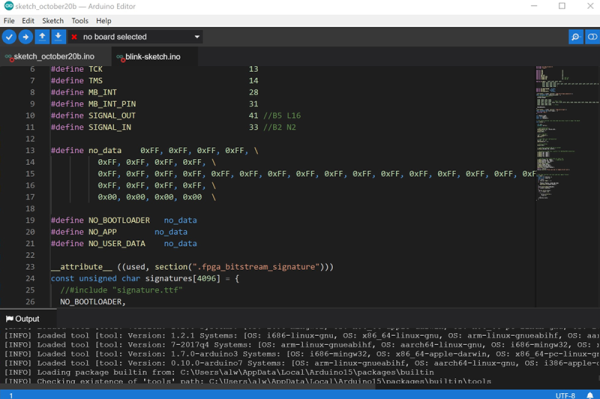
Excerpt from the SAMD wiring_analog.c file in the Arduino Core repo.

While developing a shield that interfaces to 24 V systems, the development team noticed that the ADC readings on a SAMD21-based board were off by a consistent 35 mV; expanding their tests to a number of different analog pins and SAMD21 boards, they saw offsets between 25 mV and 57 mV. It seems like this offset was a known issue; Arduino actually provides code to calibrate the ADC on SAMD boards, which will “fix” the problem with software gain and offset factors, although this can reduce the range of the ADC slightly. Still, having to correct for this level of error on a microcontroller ADC in 2019 — or even 2015 when the code was written — seems really wrong.

After writing their own ADC read routine that produced errors of only between 1 mV and 5 mV (1 to 6 LSB), the team turned their attention to the Arduino code. That code disables the ADC between measurements, and when it is re-enabled for each measurement, the first result needs to be discarded. It turns out that the Arduino code doesn’t wait for the first, garbage, result to finish before starting the next one. That is enough to cause the observed offset issue.

It seems odd to us that such a bug would go unnoticed for so long, but we’ve all seen stranger things happen. There are instructions on the blog page on how to quickly test this bug. We didn’t have a SAMD21-based Arduino available for testing before press time, but if you’ve got one handy and can replicate these experiments to verify the results, definitely let us know in the comments section below.

If you don’t have an Arduino board with a SAMD21 uC, you can find out more about them here.

Arduino On MBed

Sometimes it seems like Arduino is everywhere. However, with a new glut of IoT processors, it must be quite a task to keep the Arduino core on all of them. Writing on the Arduino blog, [Martino Facchin], Arduino’s chief of firmware development, talks about the problem they faced supporting two new boards from Nordic.

The boards, the Nano 33 BLE and Nano 33 BLE Sense are based on an ARM Cortex M4 CPU from Nordic. The obvious answer, of course, is to port the Arduino core over from scratch. However, the team didn’t want to spend the time for just a couple of boards. They considered using the Nordic libraries to interact with the hardware, but since that is closed source, it didn’t really fit with Arduino’s sensitivities. However, in the end, they took a third approach which could be a very interesting development: they ported the Arduino core to the Mbed OS. There’s even an example of loading a sketch on top of Mbed available from [Jan Jongboom].

Continue reading “Arduino On MBed”

3D Printed Pen Plotter Is As Big As You Need It To Be

There’s nothing quite like building something to your own personal specifications. It’s why desktop 3D printers are such a powerful tool, and why this scalable plotter from the [Lost Projects Office] is so appealing. You just print out the end pieces and then pair it with rods of your desired length. If you’ve got some unusually large computer-controlled scribbling in mind, this is the project for you.

The design, which the team calls the Deep Ink Diver (d.i.d) is inspired by another plotter that [JuanGg] created. While the fundamentals are the same, d.i.d admittedly looks quite a bit more polished. In fact, if your 3D printed parts look good enough, this could probably pass for a commercial product.

For the electronics, the plotter uses an Arduino Uno and a matching CNC Shield. Two NEMA 17 stepper motors are used for motion: one to spin the rod that advances the paper, and the other connected to a standard GT2 belt and pulley to move the pen back and forth.

We particularly like the way [Lost Projects Office] handled lifting the pen off the paper. In the original design a solenoid was used, which took a bit of extra circuitry to drive from the CNC Shield. But for the d.i.d, a standard SG90 servo is used to lift up the arm that the pen is attached to. A small piece of elastic puts tension on the assembly so it will drop back down when the servo releases.

If this plotter isn’t quite what you’re after, don’t worry. There’s more where that came from. We’ve seen a number of very interesting 3D printed plotters that are just begging for a spot in your OctoPrint queue.

Air Hockey Table Is A Breeze To Build

Many of us have considered buying an air hockey table, but are put off by the price. And even if the money is there, those things take up a lot of space. How often are you really going to use it?

This DIY air hockey table is the answer. It’s big enough to be fun, but small and light enough to easily stow away in the off-season. At ~$50, it’s a cheap build, provided you have a vacuum cleaner that can switch to blower mode. The strikers, goals, corner guards, and scoreboard enclosure are all 3D-printed, while the pucks and playfield are laser-cut acrylic. [Technovation] glued acrylic feet to the strikers to help them last longer.

The scoreboard is an Arduino Uno plus an LCD that changes color to match the current winner. Scoring must be entered manually with button presses, but we think it would be fairly easy to detect a puck in the goal with a force or weight sensor or something. For now, the RGB LEDs around the edge are controlled separately with a remote. The ultimate goal is to make the Arduino do it. Shoot past the break and cross-check it out.

Already have a table? Had it so long, no one will play you anymore? Build yourself a robotic opponent.

Continue reading “Air Hockey Table Is A Breeze To Build”

A Colorful Way To Play Chess On An ATmega328

We’ve all seen those chess computers that consist out of a physical playing field, and a built-in computer that would indicate where you should put its pieces while inputting the position of your pieces in some way. These systems are usually found in a dusty cardboard box in a back room’s closet, as playing like this is fairly cumbersome, and a lot depends on the built-in chess computer.

This take by [andrei.erdei] on this decades-old concept involves an ATmega328p-based Arduino Pro Mini board, a nice wooden frame, and 4 WS2812-based 65×65 mm RGB 8×8 LED matrices, as well as some TTP223 touch sensors that allow one to control the on-board cursor. This is the sole form of input: using the UP and RIGHT buttons to select the piece to move, confirm with OK, then move to the new position. The chess program will then calculate its next position and indicate it on the LED matrix.

Using physical chess pieces isn’t required either: each 4×4 grid uses a special pattern that indicates the piece that occupies it.  This makes it highly portable, but perhaps not as fun as using physical pieces. It also kills the sheer joy of building up that collection of enemy pieces when you’ve hit that winning streak. You can look at the embedded gameplay video after the break and judge for yourself.

Continue reading “A Colorful Way To Play Chess On An ATmega328”

OTA Flash Tool Makes Fitness Tracker Hacking More Accessible

Over the last several months, [Aaron Christophel] has been working on creating a custom firmware for cheap fitness trackers. His current target is the “D6 Tracker” from a company called MPOW, which can be had for as little as $7 USD. The ultimate goal is to make it so anyone will be able to write their own custom firmware for this gadget using the Arduino IDE, and with the release of his new Android application that allows wirelessly flashing the device’s firmware, it seems like he’s very close to realizing that dream.

Previously, [Aaron] had to crack open the trackers and physically connect a programmer to update the firmware on the NRF52832-based devices. That might not be a big deal for the accomplished hardware hacker, but it’s a bit of a hard sell for somebody who just wants to see their own Arduino code running on it. But with this new tool, he’s made it so you can easily switch back and forth between custom and original firmware on the D6 without even having to take it off your wrist.

After the break, you can see the video that [Aaron] has put together which talks about the process of flashing a new firmware image. It’s all very straightforward: you simply pick the device from the list of detected BLE devices, the application puts the tracker into bootloader mode, and then you select the DFU file you want to flash.

There are a couple of ready-made firmwares you can put on the D6 right now, but where’s the fun in that? [Aaron] has put together a customized version of the Arduino IDE that provides everything you need to start writing and flashing your own firmware. If you’ve ever dreamed about creating a wearable device that works exactly the way you want, it’s hard to imagine a cheaper or easier way to get in on the action.

When we last heard from [Aaron] earlier this year, he was working on the IWOWN I6HRC tracker. But it looks like the availability of those devices has since dried up. So if you’re going to try your hand at hacking the MPOW D6, it might be wise to buy a few now while they’re still cheap and easy to find.

Continue reading “OTA Flash Tool Makes Fitness Tracker Hacking More Accessible”

Launching A Custom Kerbal Panel

[Matthew Peverill] is a busy PhD student who loves to make time for a little Kerbal Space Program. He was tired of using such pedestrian controls as a keyboard and mouse for such important work, and wanted something a little more like they have down in Houston.

For this project, he’s focusing on the inputs more than anything else. The intent is not to play solely from this control panel, but to strike a balance between fun inputs and accurate control without screwing up favorite game play modes. It’s based on an Arduino Due, and uses some custom I²C multiplexer boards to wrangle all the various inputs.

We love the look of this panel, especially the appropriately Futura-fonted labels and all the toggle switches. Matthew took inspiration and guidance for this project from a couple of sources, so he’s definitely following in the Hackaday spirit of standing on the shoulders of giants. He’s moved through two prototypes and is working out the bugs before making the next one. The final version will be made of backlit transparent acrylic, and you know we can’t wait to see that.

What, you don’t have access to a laser cutter? Just build a control panel into an old Heathkit trainer or something.