Vodafone USB 3G Modem Driver From Mbed

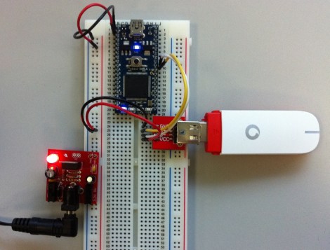
Wow, that’s a really simple hardware setup to supply your device with a 3G Internet connection. Better yet, the software side is just as simple thanks to the Vodafone USB Modem library for mbed. It will work for any of the cell data plans offered by Vodafone. The only problem you may have is not living in one of the 30 countries serviced by the telco.

The dongle seen at the right is sold by Vodafone and is meant to be used for Internet data, so you won’t be doing anything that might get your SIM banned. Connecting to the network is a one-liner thanks to the previously mentioned library. From there, gets and posts can be done with your favorite package. The  Hello World example uses HTTPClient. And since the mbed is simply an ARM platform it shouldn’t be hard to use the library with the ARM chip of your choice.

Turning A 600 Mil Chip To 300 Mil

We’ve seen a few builds featuring NXP’s LPC1114 microcontroller before. This chip – the only breadboard friendly ARM microcontroller available – comes in a ‘still a little too large for prototyping’ 600 mil, 28 pin package. We won’t hazard a guess why NXP chose this rather large package, but the good news is it’s possible to shave this chip down to the more common 300 mil, 28-pin package used by AVRs and PICs.

In the video tutorial of this procedure, the chip is first taped down to a desktop CNC mill. 150 mil on each side of the die are removed, exposing the very cool-looking pattern of leads coming out of the chip. This isn’t enough area to solder, so the chip had to be further milled to expose some of the internal wiring.

After soldering everything to a set of pins, the new 300 mil package is covered in epoxy putty, milled down again into a nice cube shape and painted. Yes, the modified chip does work, and no, we can’t figure out why NXP chose a 600 mil package for this microcontroller over the far more common 300 mil chip.

Video after the break. Tip ‘o the hat to [Ian] for sending this one in.

Continue reading “Turning A 600 Mil Chip To 300 Mil”

BeagleBone Powers This Networked LED Marquee

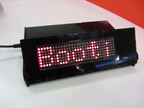
[Mahmut] calls this project SmartBox. It’s a BeagleBone controlled LED marquee which can pull down information off of the Internet.

The project started with the display itself. [Mahmut] used six 5×7 LED modules to populate a circuit board he produced himself. The low side of the modules is controlled by some MBI5026 constant current drivers, with PNP transistors on the high side. The display connects to the BeagleBone ARM board using a couple of IDC ribbon cable connectors. With that up and running he started working on the enclosure. The display board was modeled in Google SketchUp to ensure that the case design would fit it properly. The laser cut acrylic case is in two parts, the base holds the driver electronics, with a hinged section for adjusting the angle of the marquee.

So far there are a few different connectivity features which are shown off in the clip after the break. The BeagleBone has the ability to pull down Twitter feeds, notify about incoming email, and scroll messages.

Continue reading “BeagleBone Powers This Networked LED Marquee”

PWM On The Stellaris Launchpad

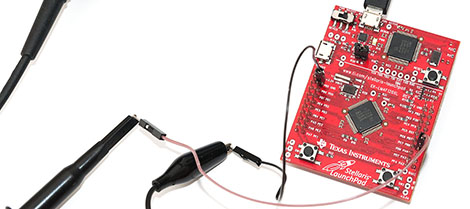
[Joonas] has been following TI’s ‘getting started’ tutorials for their new Stellaris Launchpad. Everything had been going swimmingly until [Joonas] reached the fourth tutorial on interrupts. To the ire of LEDs the world over, implementing PWM on the new Stellaris Launchpad is a somewhat difficult task. After banging his head against the documentation for hours, [Joonas] finally cracked his PWM problem and decided to share his discoveries with the world.

The Stellaris has a PWM mode for its six hardware timers, but unfortunately there are no PWM units on the chip. Solving this problem required making two 16-bit timers out of a single 32-bit one. This allowed [Joonas] to specify a ‘load’ and ‘match’ value.

After coding this up, [Joonas] discovered the PWM timer only works on two of the Launchpad’s pins. Hours of Googling later, he had real PWM on his Stellaris Launchpad.

Given the amount of time [Joonas] spent on this problem, we’re glad to help all the other frustrated Stellaris tinkerers out there by sharing this.

Guide To Developing With The Stellaris Launchpad On A Linux Box

So you picked up your very own Stellaris Launchpad, a TI ARM dev board which can be in your hands for just five bones. They do distribute several free IDEs which are not size-limited but perhaps you’re more of a text editor and command line sort of person. Well you’re in luck. There’s now a guide to show you how to code for and program the Stellaris Launchpad from a Linux box with using one of the IDEs.

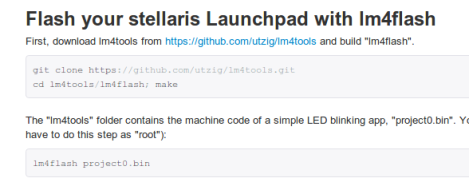
There are two main things that are needed to accomplish this. The first is a cross-compiling toolchain for the ARM architecture; something that has been readily available for quite some time. The second is a way to talk to the in-built Stellaris programmer from a Linux machine. The hardware uses the ICDI protocol, and as we reported last week the lm4tools project can be used for this purpose. The guide also covers building the StellarisWare package. It’s not a requirement, but it makes using the peripherals much easier and provides names for the I/O pins, etc.

Our favorite for debugging microcontroller projects is OpenOCD. From this thread post it looks like there is now ICDI support in the development branch of the software if you don’t mind compiling from source.

.NET For The STM32 F4 Discovery Board

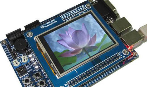
Here’s a technique that will let you use the .NET framework on an STM32 Discovery board. [Singular Engineer] was happy to learn that the .NET Micro Framework had been ported for STM32 chips. It’s doesn’t look like the port has hit a stable version yet, but these instructions will be enough to get you up and running. This lets you use managed code in the C# language to program an embedded device: the STM32 F4 Discovery board.

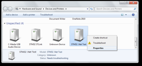
After flashing a new bootloader to the board a driver needs to be added for Windows to communicate with it. Above you can see that the board will enumerate as ‘STM32 .Net Test’. Once the driver is installed the rest of the firmware can be loaded on the board using a GUI supplied with the NETMF for STM32 package. That takes care of prepping the hardware, the rest is a painless process of configuring Visual Studio to use the board as a target. The ‘Hello World’ application then uses C# to blink an LED.

Debugging The Stellaris With OpenOCD

It looks as though Texas Instruments are really reaching out to the hacker community with their new ARM-powered Stellaris dev board. On the Stellarisiti forums, a member asked about the debugging options for the Stellaris board. The Stellaris already features an In-Circuit Debug Interface (ICDI), but unfortunately it’s a little hard to get working in Linux-ey environments.

One of the devs for the Open On-Chip Debugger was already talking with TI to get the ICDI spec released for the Stellaris board. TI released the info, and after quite a bit of work, everything is open for all to see.

Right now, OpenOCD support for the Stellaris is still incomplete, but there is an project up on the Gits that allows for multi-platform development for TI’s new board.

Needless to say, getting everything up and running is still a chore. That’s not really a concern, though; the Stellaris has only been around for a few months and it takes devs time to put all the required tools into nice, neat packages. We’re just glad TI is being so forthcoming with the relevant documentation, lest development becomes a million times harder.