Another Desktop LED Xmas Tree!

We love it when someone takes inspiration from one of our posts and comes up with their own twist on it. [Matthew] liked one builds he saw on Hackaday so much, he built his own LED desktop Xmas tree!

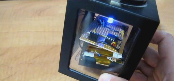
[Matthew] was inspired by [designer2k2]’s DIY desktop Xmas tree that was posted in October. To get started, he found a set of concentric WS2812 rings over on Ali Express. The five rings total 93 LEDs, plus a single WS2812 for the top of the tree. He also got a laser cut tree model from Thingiverse and had it cut, combining the LED rings with the tree in the final product

The whole thing running on a Digispark USB Development Board from DigiStump, the same as the original project. There aren’t many details in the video, but [Matthew] has put links to where he got the rings and the tree, the laser cutting service, a link to the DigiStump website as well as a link to [designer2k2]’s original tree project. There’s no source code yet, but [Matthew] says a link to it is coming along with some more pictures.

Continue reading “Another Desktop LED Xmas Tree!”

Modular Tap-Dancing Robot Can Shuffle Ball Change

Electromechanical solenoids are pretty cool devices. Move some current through an electromagnet and you can push a load around or pull it. If you’re MIT student [Lining Yao], you can use them to dance. [Lining] built TapBot, a re-configurable set of tap-dancing robots that are both modular and modern. She even rolled her own solenoids.

The one with the eye stalk is the bridge, and it’s connected to a computer over FTDI. The other nodes attach to the bridge and each other with small magnets that are designed to flip around freely to make the connections. These links are just physical, though. The nodes must also be connected with ribbon cables.

Each of the nodes is controlled by an ATtiny45 and has a MOSFET to drive the solenoid at 8-12 V. [Lining] snapped a small coin magnet to the end of each solenoid slug to provide a bigger surface area that acts like a tap shoe. TapBot can be programmed with one of several pre-built tap patterns, and these can be combined to make new sequences. The curtain goes up after the break.

There are other ways to make things dance, like muscle wire. Check out this whiteboard pen that uses nitinol to dance to Duke Nukem.

Continue reading “Modular Tap-Dancing Robot Can Shuffle Ball Change”

7 LED’s, 2 Pins – Beat That, Charlieplexing

[Tim]’s Dice10 is an exercise in minimalism. Building an electronic dice using an ATtiny10 with code that fits within 1kB is not too difficult. Charlieplexing the LED’s would have used three of the four available GPIO pins. [Tim] upped the game by using just two GPIO pins to drive the seven LED’s for the dice. A third GPIO is used as a touch button input. Besides the ATtiny and the LED’s, the only other component used is a capacitor across the supply inputs.

2 GPIO for 7 LED's
2 GPIO for 7 LED’s

The LED’s are grouped in three pairs of two LED’s and a single centre LED. Usually, Charlieplexed LED’s are connected across pairs of GPIO pins. But his scheme includes connections to the 5V and GND terminals, besides the two GPIO pins. Building a truth table makes it easy to figure out what’s going on.

STATE PB2 PB0 LED's
1     Z   Z   --
2     L   Z   LED 1/2
3     H   Z   LED 3/4
4     Z   L   LED 5/6
5     Z   H   --
6     H   L   LED9
7     L   H   --
8     H   H   --
9     L   L   --

Only the logic states used are listed in the table. It’s possible to add two more LED’s between PB0 and GND and one more anti-parallel with LED9, making a total of 10 LED’s driven by two pins. That’s quite a hack. The important thing here is to have two LED’s in series in the arms that connect to either 5V or GND.

[Tim] has posted  the code and hardware source files on his Github repo, and his blog post has some additional details on how he solved the problem.

If you’re looking for more inspirations on minimal dice designs, check this “PIC powered pair of electronic dice” which uses a PIC 12F629 with five outputs driving a pair of 7 pips to make a dual dice.

1kb-thumb

If you have a cool project in mind, there is still plenty of time to enter the 1 kB Challenge! Deadline is January 5, so check it out and fire up your assemblers!

USB Etch-a-Sketch-Style Mouse Is More Analog Than You’d Think

[Mitxela] wanted to build a different kind of mouse, one that worked like an Etch-a-Sketch toy with one X knob and one Y knob. Armed with some rotary encoders and a microcontroller, that shouldn’t be hard. But when you use a pin-limited ATtiny85, you are going to need some tricks.

The encoders put out a two-bit Gray code and close a button when you depress them. Plus you need some pins for the V-USB stack to handle the USB interface. [Mitxela] decided to convert the encoders  to output analog voltages using a simple resistor DAC. That would only require two analog inputs, and another anlaog input could read both switches.

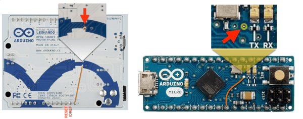
One problem: there still wasn’t quite enough I/O. Of course, with AVRs you can always repurpose the reset pin as an analog pin, but you lose the ability to program the device at low voltage. And naturally, there’s a workaround for this too, allowing you to keep the reset pin and still read its analog value. You just have to make sure that value doesn’t go below about 2.5V so the device stays out of reset. Once that was in place, the rest went easy, as you can see in the video below.

Continue reading “USB Etch-a-Sketch-Style Mouse Is More Analog Than You’d Think”

Making A Spectrum Analyzer The Wrong Way On An ATtiny85

Everyone’s a critic, but it’s hard to argue with success. And that’s exactly what [agp.cooper] has with his ATtiny85-based spectrum analyzer devices.

The “normal” way to build a spectrum analyzer is to collect a bunch of samples and run a Fast Fourier Transform (FFT) on them all in one shot. As the name implies, the FFT is fast, and the result is the frequency components of the sampled data. [agp.cooper]’s “wrong” way to do it takes the Goertzel algorithm, which is used for detecting the intensity of a particular frequency, and scanning across the frequency range of interest. It’s a lot slower than a single FFT but, importantly for the ATtiny85 that he implements this on, it’s less demanding of the RAM.

Continue reading “Making A Spectrum Analyzer The Wrong Way On An ATtiny85”

Tiny Tunes On An ATtiny13

When you take a microcontroller class in university, one of the early labs they have you drudge through on your way to, promised, mastery over all things embedded, is a tiny music generator.

It’s a more challenging lab than one would expect. It takes understanding the clock of the microcontroller and its sometimes temperamental nature. It takes a clear mental picture of interrupts, and is likely one of the first experiences a burgeoning designer will have worrying about the execution time of one of their loops. Also tables, data structures, and more. It even requires them to go out of their comfort zone a learn about an unrelated field, a challenge often faced in practicing engineering.

Luckily [Łukasz Podkalicki] has done a great job of documenting the adventure. He’s got everything from the schematic and code to the PWM traces on the oscilloscope.

It’s also worth mentioning that he’s got a few other really nice tutorials for the ATtiny13 microcontroller on his blog. A tiny party light generator and a IR receiver among them.

DIY I2C Devices With ATtiny85

[Pawel] has a weather station, and its nerve-center is a Raspberry Pi. He wanted to include a light sensor but the problem is, the Pi doesn’t have a built-in ADC to read the voltage off the light-dependent resistor that he (presumably) had in his junk box. You can, of course, buy I2C ADC chips and modules, but when you’ve already got a microcontroller that has ADC peripherals on board, why bother?

[Pawel] wired up a tremendously simple circuit, downloaded some I2C slave-mode code, and added an LED for good measure. It’s all up on GitHub if you’re interested.

cropped_shot_2016-10-21-112958
Bright by Day, Dark by Night!

We’re covering this because we rarely see people coding for I2C slave devices. Everyone and their mom uses I2C to connect to sensors, for which the Arduino “Wire” library or “i2c-tools” on the Pi do just fine. But what do you do when you want to make the I2C device? [Pawel]’s project makes use of TinyWireS, a slave-mode SPI and I2C library for AVR ATtiny Arduino projects.

Here, [Pawel] just wanted a light sensor. But if you’re building your own devices, the sky is the limit. What’s the most esoteric I2C sensor that you can imagine? (And is it really the case that we haven’t seen an I2C slave device hack since 2010?)