We recently reported on the amateur scientific work of Forrest Mims. Forrest is somewhat unique in being an amateur scientist who has consistently published his work in leading scientific journals. One area of scientific investigation has however attracted amateur scientific contributions of the highest quality almost since its inception, amateur astronomy.
Will Hay – Amateur Astronomer
You’ve likely heard of amateur astronomers like David Levy co-discoverer of the Comet Shoemaker–Levy 9 comet, and citizen science projects like galaxy zoo. But the history of amateur astronomy goes back far further than this, in fact as far back as 1781 William Herschel discovered the planet Uranus while employed as a Musician. Another entertainer of sorts, 1930s British comic actor, Will Hay, also made significant contributions discovering a “Great White Spot” on Saturn in-between films roles. Will was an avid amateur astronomer who regularly published his observations.
His belief that astronomy allows us to see humanity’s place in the universe in its true proportion led him to claim “If we were all astronomers there’d be no more war”.
While Will recorded his observations, hand drawn, in a log book. Modern astronomers digitally image the night sky. Digital cameras are of course optimized around the human visual system (as we recently discussed) making them less than ideal for astrophotography. Hackers have therefore made a number of innovations, one of the more audacious being the removal of the Bayer filter:
I learned to program FORTRAN IV in the spring of 1968 while working as an engineering technician in water resources. One of the engineers knew of my interest in computers and asked if I would like to learn FORTRAN. He needed to calculate the biological oxygen demand in streams but didn’t have any interest in programming. I jumped at the chance.
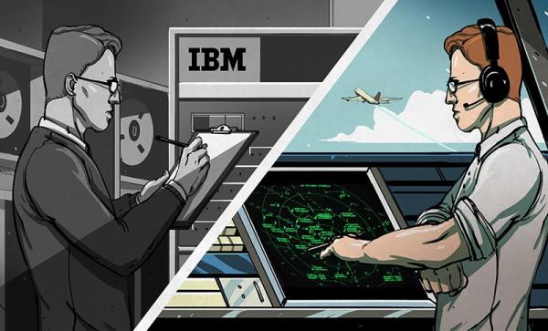
This was the days of big iron when the term computer meant a room full of heavily air-conditioned equipment. The State University of New York at Buffalo had an IBM 704 but they soon upgraded to a CDC 6400. To help pay for it they were inviting people to attend a seminar on FORTRAN so they could use the system. My job was with a small State of NY office and getting approval for me to attend was surprisingly easy.
Off I went for 6 weeks of training on one night a week. I still have my black “A Guide to Fortran IV Programming” by [Daniel McCracken]. For years, this was the FORTRAN bible, commonly referred to as just “McCracken”.
The programming went well and somewhere out there is a very old paper with a reference to the results it generated about the Chadakoin River flowing through Jamestown, NY.
This is FORTRAN’s strength – scientific calculations. It’s name says it: FORmula TRANslation.
Origins and FORTRAN IV
[John W. Backus] suggested to IBM a language to replace assembly language. Development began in 1953 for the IBM 704 and the project reached fruition in 1957. Not only was it the first general purpose high-level language, just beating out COBOL and LISP, but its compiler optimized the code since it needed to compete head-on with assembly language. It was the C compiler of its day in that regard.
That was not the only reason it attained success. Reducing the number of punched cards needed for a program by a factor of 20 over assembly helped considerably.
In those days, you needed to use a key punch to create a deck of punch cards. To be really good you had to know how to create a programming card that would let you skip through the fields on a FORTRAN card, or how to edit a card by duplicating it and holding one of the cards in place while you typed in new characters. Because of my fascination with computers I’d taken a key punching and automation machines class in high school so I was all set.
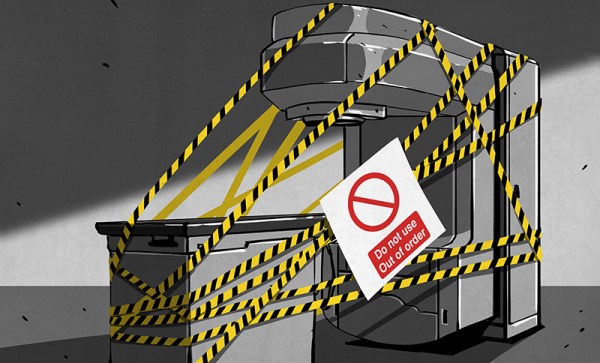
The Therac-25 was not a device anyone was happy to see. It was a radiation therapy machine. In layman’s terms it was a “cancer zapper”; a linear accelerator with a human as its target. Using X-rays or a beam of electrons, radiation therapy machines kill cancerous tissue, even deep inside the body. These room-sized medical devices would always cause some collateral damage to healthy tissue around the tumors. As with chemotherapy, the hope is that the net effect heals the patient more than it harms them. For six unfortunate patients in 1986 and 1987, the Therac-25 did the unthinkable: it exposed them to massive overdoses of radiation, killing four and leaving two others with lifelong injuries. During the investigation, it was determined that the root cause of the problem was twofold. Firstly, the software controlling the machine contained bugs which proved to be fatal. Secondly, the design of the machine relied on the controlling computer alone for safety. There were no hardware interlocks or supervisory circuits to ensure that software bugs couldn’t result in catastrophic failures.
The case of the Therac-25 has become one of the most well-known killer software bugs in history. Several universities use the case as a cautionary tale of what can go wrong, and how investigations can be lead astray. Much of this is due to the work of [Nancy Leveson], a software safety expert who exhaustively researched the incidents and resulting lawsuits. Much of the information published about the Therac (including this article) is based upon her research and 1993 paper with [Clark Turner] entitled “An Investigation of the Therac-25 Accidents”. [Nancy] has since published updated information in a second paper which is also included in her book.
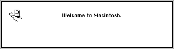
A few years ago, [Steve] of Big Mess ‘O Wires fame stuffed one of the first Macintosh computers into an FPGA. While the project worked and was able to run System 6 on a virtual CPU, there were a few problems: it wasn’t exactly stable, and there was no support for a keyboard, sound, SCSI, or serial ports.
Now, there’s a new tiny FPGA board around, and this one is perfectly designed to fit the original Macintosh on it. It’s much more stable, and there is a floppy disk emulator on the horizon, just so you won’t have to deal with all those 400k 3.5″ disks anymore.
[Steve]’s brand new Mac Plus is based on the MiST board, an FPGA board that was originally designed to emulate the first Amigas and the Atari SE on an FPGA and a separate ARM CPU. There’s already been a lot of classic computers ported to the MiST, and the classic all-in-one Macs are the last project that’s left.
In the video below, you can see the MiST board running the classic System 6 at SVGA resolution. That means MacPaint and Shufflepuck in one compact board using modern hardware.
Everyone has their favorite process for PCB fabrication, as long as you’re a happy hacker I don’t think it really matters. But in this post I thought it might be interesting to describe my personal process, and some of the options available.
Making your own at home
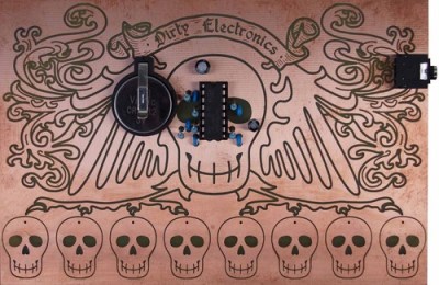
The Dirty Electronics Skull Etching Synth a great looking maskless board.
Etching is the classic PCB fabrication option for the home hacker. It’s been many, many years since I etched a PCBs but it can produce interesting results. Some people don’t like it, and I’d personally tend to avoid it as a messy and finicky process. But, if you only need 1 or 2 layer boards with large features (through-hole components are best of course) it can be a viable option. In some cases, I think etched boards look awesome and are a great fit. One example is the skull etching shown to the right. The oxidation and discoloration of the boards adds to the design aesthetic in this case.
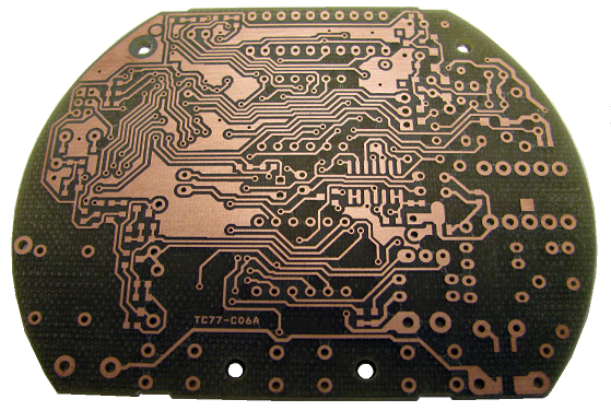
A simple design milled on an Accurate CNC
For those with a bigger budget a professional milling machine might be a viable choice. I’ve used an Accurate CNC in the past (LPKF and others make mills too), but this is an expensive option (no online pricing, but if $10,000 USD is a lot for you don’t bother). The accurate mill is pretty awesome, it can be fitted with a vacuum bed, automatic tool changer and vision system for alignment. The mill can produce high quality two layer boards with all the holes and vias drilled out. The final step of filling the vias is however manual, but compared to etched boards the results are pretty professional (the mill itself uses milled PCBs!). They claim a 0.1mm (4 mil) track size, I’ve never tried tracks this small but surface mount components were not a problem.
While a fun toy, it’s worth considering if you really need a PCB mill. The only case where they’re really valuable is if you want to be able to iterate over a design with less than a days turn around. This can be useful in RF or low noise designs where you might want to experiment with different layouts, but for other projects the price of a good mill can pay for quick turn around (1 or 2 days from order submission to delivery) on a lot of boards.
Commercial Fabrication
Years ago commercial fabrication used to be a very expensive and finicky process. For the most part you’d need to order a full panel putting the service outside of most hobbyists reach. Generating gerbers and drill files to the fabs specification could also be a process fraught with complication.
These days services that aggregate designs onto a single panel and break them out for distribution are common. For my work I mostly stick with OSHPark and SeeedStudio whose services complement each other well. I’ve also used Itead and found them compatible with Seeed (with the added benefit that they supply free boards for open projects).
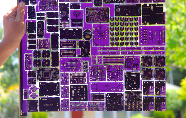
Using OSHPark gives me the warm fuzzies. A child of the hacker community, born out of DorkbotPDX, all OSHPark’s boards are fabbed in the US (check out the great amphour interview for more details). Their services are limited to either 2 or 4 layer boards (always in purple, and always coated with gold (ENIG)), in 6×6 (6 mil traces with 6 mil spacing) or 5×5. I rarely attempt BGA boards so the 2 layer service works out great for me. OSHPark’s minimum order is 3 boards, which is perfect for prototyping. The gold plating also provides a nice finish, which both protects the board from oxidation and provides a nice surface to solder to. The main reason I use OSHPark however is that they’re cheap for small boards and have a relatively fast turn around (I recently purchased 3 tiny 20x15mm boards for $2.40 including shipping which was unbeatable). From OSHPark in the US to the UK my boards take about 2 weeks to arrive. They’ve also automatically upgrade boards to their super-swift service for free when there’s spare capacity. Their service is pretty slick, and provides a rendering of the gerbers prior to ordering as a final check which comes in very handy.
Seeed on the other hand are much cheaper for larger size boards and volume orders. They also provide more color and finishing options. The cheapest option at Seeed is green PCBs with HASL finish (hot air solder leveling). From Seeed, my boards usually take about a month to arrive (there are a few delivery options, but in my experience this is about as fast as it gets and faster shipping services often make using Seeed less attractive).
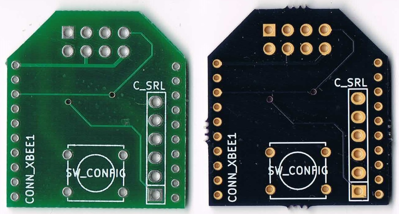
The image to the right shows a couple of very simple boards I had manufactured at both OSHPark and Seeed. I’ve never had a fabrication issues with boards from either service (though I prefer the ENIG finish).
Partly due to the limitations imposed by using commercial fabs I pipeline my projects. I send projects out to fab early in the design process and then switch to another design. When the board comes back I bring it up, bodge as required, and iterate over the layout. This works well with a two-week turn around, so I mostly use OSHPark while prototyping.
My boards also tend to be quite small (Arduino shield size or a little bigger). With small boards like this OSHPark is usually on-par or cheaper than ordering from Seeed (whose minimum quantity is 10 boards). With boards of about 100x100mm or larger I consider Seeed as they become significantly cheaper.
As a hobbyist I also rarely need huge numbers of boards, but for workshops when I need 10 or 20 boards I order from Seeed based on the final iteration of my prototypes. This is not only much cheaper than OSHPark, but I can get boards in a variety of colors to make workshops more interesting too.
This post has described some of the available options and my personal process. I hope it’s been interesting, but I’d love to hear about your favorite fabrication techniques, services and experiences both good and bad too. Please comment below!
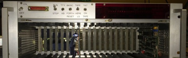
Today when you want to upgrade your computer you slap in a card, back in the early 80’s things were not always as simple. When [Carsten] was digging around the house he found his old, and heavily modified Rockwell AIM 65 single board computer, flipped the switch and the primitive 6502 machine popped to life.
Added to the computer was a pile of wires and PCB’s in order to expand the RAM, the I/O to form a “crate bus” and of course tons of LED blinkenlights! On that bus a few cards were installed, including a decoder board to handle all the slots, a monitor controller, a massive GPIO card, and even a universal EEPROM programmer.
If that was not enough there was even a OS upgrade from the standard issue BASIC, to a dual-boot BASIC and FORTH. Though again unlike today where upgrading your OS requires a button click and a reboot, making all these upgrades are planned out on paper, which were scanned for any retro computer buff to pour through.
[Carsten] posted a video of this computer loading the CRT initilization program from a cassette. You can watch, but shouldn’t listen to that video here.
In the late 1800s, a railway engineer named Philbert Maurice d’Ocagne was part of a group of men faced with the task of expanding the French rail system. Before a single rail could be laid, the intended path had to be laid out and the terrain made level. This type of engineering involves a lot of cut and fill calculations, which determine where dirt must be added or removed. The goal of earthwork is to create a gentle grade and to minimize the work needed to create embankments.
In the course of the project, d’Ocagne came up with an elegant, reusable solution to quickly solve these critical calculations. Most impressively, he did it with little more than a pen, some paper, and a straightedge. By developing and using a method which he called nomography, d’Ocagne was able to perform all the necessary calculations that made the gentle curves and slopes of the French railway possible.


 This was the days of big iron when the term computer meant a room full of heavily air-conditioned equipment. The State University of New York at Buffalo had an IBM 704 but they soon upgraded to a CDC 6400. To help pay for it they were inviting people to attend a seminar on FORTRAN so they could use the system. My job was with a small State of NY office and getting approval for me to attend was surprisingly easy.