The Vintage Computer Festival East was last weekend, and now it’s time to wrap everything up. We’re going to start this off with a video of the biggest, most intolerable jerk on the planet walking around the boardwalk at Ashbury Park. Thanks to [Fran] for filming it.
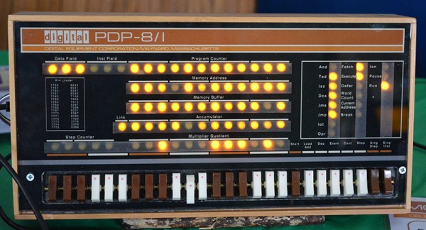
That video, despite the wretched casting director, included the reveal of the PDP Straight-8, the 50-year-old minicomputer that was repaired and refurbished by [David Gesswein] just this year. You can see some pictures of that and more below, and a little more on [David]’s website.
The Amiga 1000, the original Amiga, was introduced in 1985, making this the 30th anniversary of the Commodore Amiga. Of course this needed to be represented at the Vintage Computer Festival, and [Bill Winters] and [Anthony Becker] were more than up to the task:
The guys brought with them a representation of nearly every Amiga, and also have a few neat gadgets to plug into these cool little boxes. The Amiga 1200 has been heavily upgraded with a compact flash drive. With the proper adapters and cards, this neat machine can be upgraded with Ethernet, WiFi, or just about every conceivable networking solution.
Attached to the A500 is a Gotek floppy drive emulator, a relatively standard if weird device that turns a PC floppy drive connector into a USB mass storage solution. This floppy emulator did not originally support Amiga disk formats, but with a firmware modification, everything just works. That’s a great story in itself, and something we should probably cover another time.
If you’re wondering what it was like for [Bill] and [Anthony] to dig through their garage for their exhibit, here you go.
Portable Macintoshen
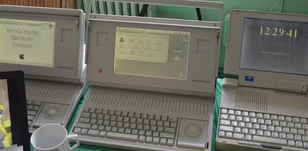
The first Macintosh was released in 1984. Macintosh users wanted a slightly more portable machine, but the first ‘luggable’ Mac wouldn’t be released until late 1989. The market was there to fill the gap, with some bizarre machines exhibited by [Matt Bergeron]:
The Outbound laptop and notebook were unlicensed clones of the Macintosh. Instead of pirating the Apple ROMs, the Outbound computers required buyers to pull the ROM chips from their Macs and install them in the slightly more portable version. This was, of course, inconvenient, and we can imagine there were more than a few ROM chips cloned.
The Dynamac was a different beast, using the entire PCB from a mac SE or SE/30. To this, the creators of the Dynamac added a custom video card and electroluminescent display that was also capable of driving an external monitor. Very cool stuff.
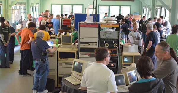
The Vintage Computer Festival last weekend featured racks and racks of old minicomputers, enough terminals for an entire lab, and enough ancient storage devices to save a YouTube video. These storage devices – hard disks, tape readers, and 8″ disk drives – were only connected to vintage hardware, with one exception: a DEC RL02 drive connected to a modern laptop via USB.
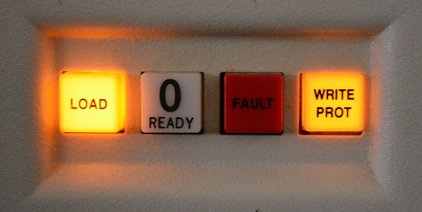
The DEC RL02 drive is the closest you’re going to get to a modern mechanical hard drive with these old machines. It’s a huge rack unit with removable platters that can hold 10 Megabytes of storage. [Chris] found one of these old drives and because he wanted to get into FPGA development, decided to create a USB adapter for this huge, old drive.
The hardware isn’t too terribly complex, with a microcontroller and an FPGA that exposes the contents of the drive over USB mass storage. For anyone trying to bootstrap a PDP-11 or -8 system, [Chris] could download disk images from the Internet, write them to the disk, and load up the contents of the drive from the minicomputer. Now, he’s using it with SimH to have a physical drive for an emulated system, but the controller really doesn’t care about what format the disk pack is in. If [Chris] formatted a disk pack with a FAT file system, he would have the world’s largest and heaviest USB thumb drive in the world.
Last Friday the Vintage Computer Festival was filled up with more than a dozen talks, too many for any one person to attend. We did, however, check out [Bil Herd]’s talk on system architecture, or as he likes to call it, the art and science of performance through balance. That’s an hour and fifteen minute talk there; coffee and popcorn protocols apply.
The main focus of this talk is how to design a system from the ground up, without any assumed hardware, or any specific peripherals. It all starts out with a CPU, some memory (it doesn’t matter which type), and some I/O. That’s all you need, whether you’re designing a microwave oven or a supercomputer.
The CPU for a system can be anything from a 6502 for something simple, a vector processor for doing loads of math, or have a RISC, streaming, pipelined, SIMD architecture. This choice will influence the decision of what kind of memory to use, whether it’s static or dynamic, and whether it’s big or little endian. Yes, even [Bil] is still trying to wrap his head around endianness.
MMUs, I/O chips, teletypes, character displays like the 6845, and the ANTIC, VIC, and GTIA make the cut before [Bil] mentions putting the entire system together. It’s not just a matter of connecting address and data pins and seeing the entire system run. There’s interrupts, RTCs, bus arbitration, DTACK, RAS, and CAS to take care of that. That will take several more talks to cover, but you can see the one last Friday below.
The Vintage Computer Festival in Wall, New Jersey doesn’t just attract locals; [Oscar] came all the way from Switzerland to show off his PiDP-8/I. It’s a miniature minicomputer, emulated in SimH, with blinkenlights and toggle switches mounted to a Raspberry Pi Hat.
Although the PiDP-8 is emulating a machine with thousands of discrete transistors, the design is exceptionally simple. On the board is 92 LEDs, a bunch of diodes, 26 toggle switches, a driver chip, and that’s about it. All the multiplexing for the switches and LEDs is taken care of in software. On the Raspberry Pi side, [Oscar] is able to run FOCAL, OS/8, and, like a normal-sized PDP-8, can toggle in programs manually.
Instead of having connecting to the ribbon cables coming out of RK01 disk drives and DECtapes, [Oscar] is emulating those too. All the files that would reside on old Digital storage mediums are now stuffed into USB thumb drives. A USB hub is plugged into the Pi, and when one of these USB disk packs is plugged into the hub, loading an operating system or a program is just a matter of flicking a few toggle switches.
[Oscar] has been working hard to turn the PiDP-8 into a kit, and the word around the booths is that this will happen sometime this summer. The expected price for this kit is very interesting: somewhere between $100 and $150 USD. For that price, we’d expect someone to rig up an Arduino-based paper tape reader very quickly, perhaps this afternoon.
The lowly TRS-80 doesn’t get much love in most circles; it’s constantly overshadowed by the popularity of the Apple II or computers that had graphics that weren’t terrible. For [Mike Loewen]’s VCF exhibit, he’s turning his TRS-80 into something good with SD card disk drives and custom graphics adapters.
The -80 in question is a Model 4, the fancy all-in-one version that could run CP/M. The disk drives in this computer were replaced with half-height 5 1/4″ drives, the 200ns RAM was replaced with 100ns RAM and modified to get rid of the wait states, and a hard drive is emulated on a SD card adapter thanks to an add-on from [Ian Mavric].
[Ian] is somewhat prolific in the world of TRS-80s; he reverse engineered the original hi-res graphics board and reimplemented it with video RAM chips of a more modern vintage.
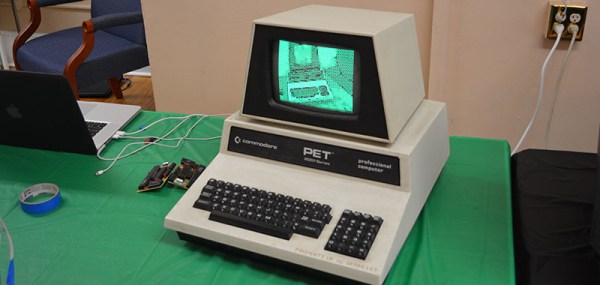
This build is an extension of [Michael]’s exhibit last year at VCF East where he displayed a video feed with PETSCII. Yes, that means displaying video with characters, not pixels.
This year, he’s doubling the number of screens, and sending everything to two iPhones in a Google Cardboard-like VR headset. Apart from the optics, the setup is pretty simple: cameras get image data, it’s sent over to a PET, and a stream of characters are sent back.
It’s impossible to film, and using it is interesting, to say the least. Video below.