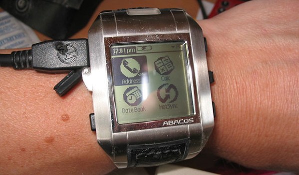
No, your eyes do not deceive you. That’s a wrist-mounted PDA. Specifically, a Fossil Wrist PDA, also known as an Abacus, that was sold from 2003 to about 2005. Yep, it’s running PalmOS. [mclien] has had this watch/PDA for a while now, and found the original 180mAh battery wasn’t cutting it anymore. He made a little modification to the watch to get a 650mAh battery in this PDA by molding a new back for it.
The original PDA used a round Lithium cell, but being ten years old, the battery technology in this smart watch is showing its years. [mclien] found two batteries (380mAh and 270mAh) that fit almost perfectly inside the battery.
The new batteries were about 3mm too thick for the existing case back, so [mclien] began by taking the old case, adding a few bits of aluminum and resin, and making a positive for a mold. Two or three layers of glass twill cloth were used to form the mold, resined up, and vacuum bagged.
After many, many attempts, [mclien] just about has the case back for this old smartwatch complete. The project build logs are actually a great read, showing exactly what doesn’t work, and are a great example of using hackaday.io as a build log, instead of just project presentation.
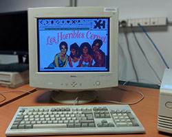
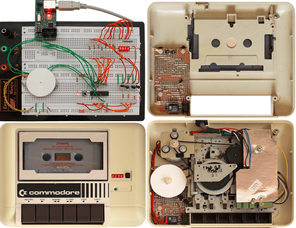
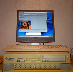 After seeing an earlier Hackaday post on old, old Unix systems loading up
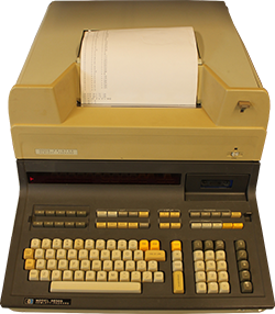 The early days of modern computing were downright weird, and the HP 9830B is a strange one indeed: it’s a gigantic calculator, running BASIC, on a CPU implemented over a dozen cards using discrete logic. In 2014 dollars, this calculator cost somewhere in the neighborhood of $50,000. [Mattis] runs a retrocomputer museum and recently acquired one of these ancient machines,


