[Bart] stood upon the shoulders of the delta 3D printer giants and created this 4 axis delta router. The router was originally created for ORD Camp, an invite only hackers gathering. Each year he creates a new thing with one main purpose: to spark conversation. In his own words “Practicality and suitability are way down the list, so go ahead and snark away. If you do, you are missing the point.”
[Bart] did things a bit differently with his delta. For motors, he went with non captive steppers. “Non captive” means that rather than a shaft, the motor has a hollow threaded nut which rotates. A lead screw (usually with an acme thread) is passed through this nut. As the motor’s nut turns, the screw is pushed or pulled through the motor, creating a linear actuator. The only major downside is that a non captive stepper motor can’t be adjusted by hand. The screw doesn’t turn and neither do any external parts of the motor. For structure, the router uses MakerSlide and v-grove wheels. The spindle is a simple brushless hobby motor and 30 amp speed control. Rather than the outrunner motors we’ve seen lately, [Bart] wisely chose an inrunner motor normally used on R/C cars. Inrunners generally have less torque than their outrunner counterparts, but they make up for this in RPM. [Bart’s] motor is capable of 30,000 RPM, which is plenty for spindle duty. We think the motor bearings will probably need an upgrade, as the original motor bearings weren’t designed for side loads. For a controller, [Bart] utilized an Azteeg X3 running Repetier.
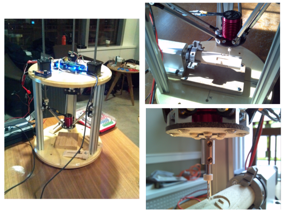
The router made a great showing at camp, and [Bart] decided it needed a 4th axis. He sourced a rotary axis from eBay. To keep the software simple, he connected the rotary axis to the extruder outputs on his controller. He was then able to hack the mach3 wrapped rotary post processor to output extruder commands. The results look great. [Bart] says the system definitely needs a tailstock, and we agree. We’re looking forward to the next update on this machine!
Continue reading “4 Axis Delta Router Says Hello World” →