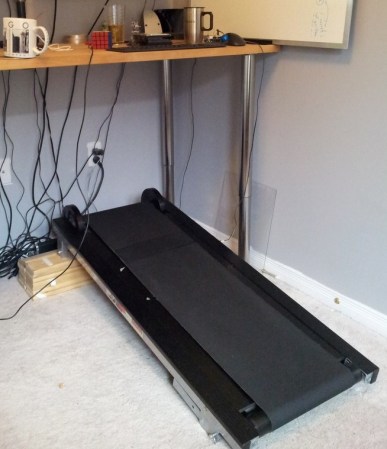
After modifying his new manual treadmill to fit under his standing desk, [Brian Peiris] found a way to let him stroll all over the internet.
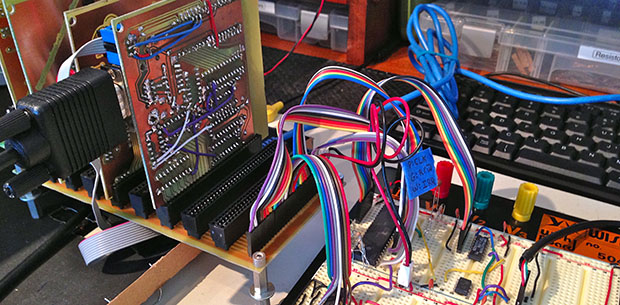
After removing the treadmill’s original time/distance display, [Peiris] reverse engineered the speed sensor to send data to an Arduino and his PC. We’ve seen a number of projects that interface treadmills with virtual worlds, but what really makes this project stand out is a simple script using the Throxy Python library which allows the treadmill to throttle his machine’s internet connection.
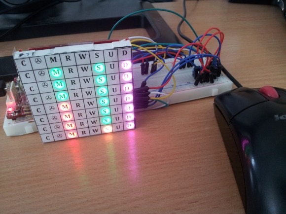
The end result is a browsing experience that reacts to how fast the user runs. In the demonstration video, you can see Peiris tiptoe through images or jog through YouTube videos. A minimum bandwidth setting keeps the connection live, so if you can’t make it all the way through that HD Netflix movie, taking a breather won’t time out the connection.
It’s certainly a great way to get in shape, or at the very least, it’ll make your ISP’s bandwidth cap feel a lot bigger.
Video after the jump.