Really, the most modern implementation of DisplayPort is the USB-C DisplayPort altmode, synonymous with “video over USB-C”, and we’d miss out if I were to skip it. Incidentally, our last two articles about talking USB-PD have given a few people a cool new toy to play with – people have commented on the articles, reached out to me for debugging help, and I’ve even seen people build the FUSB302B into their projects! Hot on the heels of that achievement, let’s reach further and conquer one more USB-C feature – one that isn’t yet openly available for us to hack on, even though it deserves to be.
For our long-time readers, it’s no surprise to see mundane capabilities denied to hackers. By now, we all know that many laptops and phones let you get a DisplayPort connection out of a USB-C port. Given that the USB-C specifications are openly available, and we’ve previously implemented a PD sink using those specifications, you’d expect that we could do DisplayPort with the same ease. Yet, the DisplayPort altmode specification is behind a VESA membership paywall, with a hefty pricetag – a practice of theirs that has been widely criticized, counter to their purpose as a standards organization and having resulted in some of their standards failing.
Not to worry, however – we can easily find an assortment of PDFs giving a high-level overview and some details of the DisplayPort altmode, and here’s my favorite! I also have a device running MicroPython with a FUSB302 chip connected, and a few DisplayPort altmode devices of mine that I can disassemble. This, turns out, is more than enough for us to reverse-engineer our way into an open-source DisplayPort altmode library!

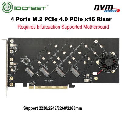 You might have heard the term “bifurcation” if you’ve been around PCIe, especially in mining or PC tinkering communities. This is splitting a PCIe slot into multiple PCIe links, and as you can imagine, it’s quite tasty of a feature for hackers; you don’t need any extra hardware, really, all you need is to add a buffer for REFCLK. See, it’s still needed by every single extra port you get – but you can’t physically just pull the same clock diffpair to all the slots at once, since that will result in stubs and, consequently, signal reflections; a REFCLK buffer chip takes the clock from the host and produces a number of identical copies of the REFCLK signal that you then pull standalone. You might have seen x16 to four NVMe slot cards online – invariably, somewhere in the corner of the card, you can spot the REFCLK buffer chip. In a perfect scenario, this is all you need to get more PCIe out of your PCIe.