[Afrotech]’s Guide To Class D Amplifiers

classd

Hang around in any of the many guitar or audiophile forums or discussion boards for long enough, and eventually you’ll come across the arguments over amplifier topologies. One of the more interesting and useful of these classes of amplifier is class d – they’re extremely efficient and when well designed can sound pretty good. [Afrotech] is here to show you how they work, and how to build a 15 Watt amp using a $3 class d amplifier chip.

The very definition of an amplifier is taking a low power signal and transforming it into a high power signal. A great way to modulate a high power signal very quickly is by modulating a square wave with pulse width modulation. A class d amplifier takes a low power input signal, uses it to modulate the duty cycle of a high power square wave, and with a little filtering, amplifies the low power input.

To demo this, [Afrotech] used TI’s TPA3122 class d amplifier chip. It’s a pretty cheap chip for being a 15 Watt stereo amplifier, and the circuit is simple enough to build on a breadboard. With a few caps, resistors, and a pair of inductors, [Afrotech] built this one-chip amplifier that’s capable of powering some pretty big speakers. It’s also very efficient – no heat sink required.

Although class d amps are extremely efficient. there are a few people out there that say because the amplifier is basically a filtered square wave, you’ll be able to hear a difference in the audio over class a or class ab amplifiers. This led to the development of class t amplifiers, basically a class d amp with a higher switching speed (Megahertz for class t, a few hundred kilohertz for class d). Still, if you need a cheap amplifier for a DIY boombox or any other high power application, you could do a lot worse than a simple class d amp.

Continue reading “[Afrotech]’s Guide To Class D Amplifiers”

Converting The Wacom Intuos Into A Cintiq

wacom

Wacom, purveyors of fine pen tablets for digital artists, basically have two product lines of pen tablets. The first, Intuos, is a great pen tablet that give an artist the ability to turn a computer into a virtual dead tree notebook. The second product line, the Cintiq, takes the same technology and adds an LCD to the mix, effectively turning a drawing tablet into a second display. [Bumhee] wanted a Cintiq, but didn’t want to pay the Cintiq price, leading him to install a display in his old Intuos tablet. It’s an amazingly simple build, making us think we’ll be seeing a few derivatives of his work in the future.

The display [Bumhee] used for this modification is a Retina display from an iPad. With the right adapter, you can easily connect one of these displays to a computer, giving you a very thin 2048×1536 9.7″ display. The initial tests to see if this mod would work on his tablet – removing the metal shield on the display, placing it on the tablet, and drawing – were a success, giving [Bumhee] the confidence to irreparably modify his tablet.

From there, the modification was a simple matter of cutting up the enclosure of the tablet, installing the display with a few screws, and installing a piece of glass over the display. Very easy, and it’s just about the only way you’re going to get a pen tablet with a small, high-resolution display for less than a thousand dollars.

Thanks [David] for sending this one in.

The Development Of A Hardware Random Number Generator

rng

[Ian] had a need for a lot of random numbers. There are dozens of commercial offerings when it comes to RNGs, but there are also hundreds of different ways for an electronics hobbyist to shoot random bits at a serial port. One of these methods is an RNG based on the avalanche breakdown noise in a PN junction. As with any circuit in hobbyist electronics, there are dozens of prototypes floating out there on the web, but not too many finished projects. [Ian] decided he would build one of these RNGs as a prototype and bring it to something resembling a finished project.

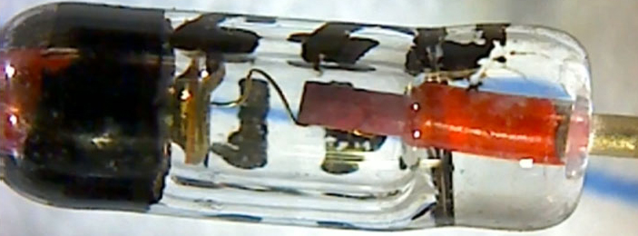
An avalanche noise RNG takes advantage of the fact that a strongly reverse-biased PN junction, like one found in a transistor, will create a condition where one electron knocks another electron out of place, leading to a sustained chain reaction. It’s quantum, it’s chaotic, it makes for a great source for a random number generator, and there are already dozens of prototype circuits around the Internet.

[Ian] took one of these circuit designs by [Will Ware] and started the iterations that would lead to a finished design. Round one was a simple PCB with the basic circuit and a power supply. Just a few transistors, resistors, and a DC/DC boost converter. Confirming the circuit was generating noise, the next iteration brought in an ADC and an ARM micro with a USB interface. Iterating over this again with an improved ADC – 20 megasamples per second – the design finally reached a point where a final PCB could be designed.

In the end, [Ian] turned a simple circuit that could have been built on a breadboard into a USB device that throws 9kB/s of random data into a computer. The data are actually good, too: the project passed most of the Dieharder test suite, making it very useful for whatever crypto or gaming application [Ian] has in mind.

OLED display, blue LED and Smartcard

Developed On Hackaday: We Have Final Prototypes!

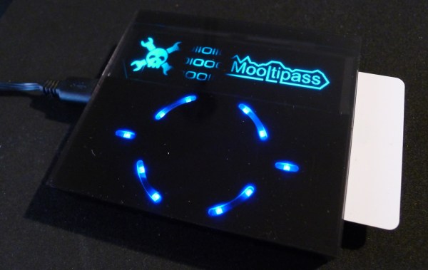
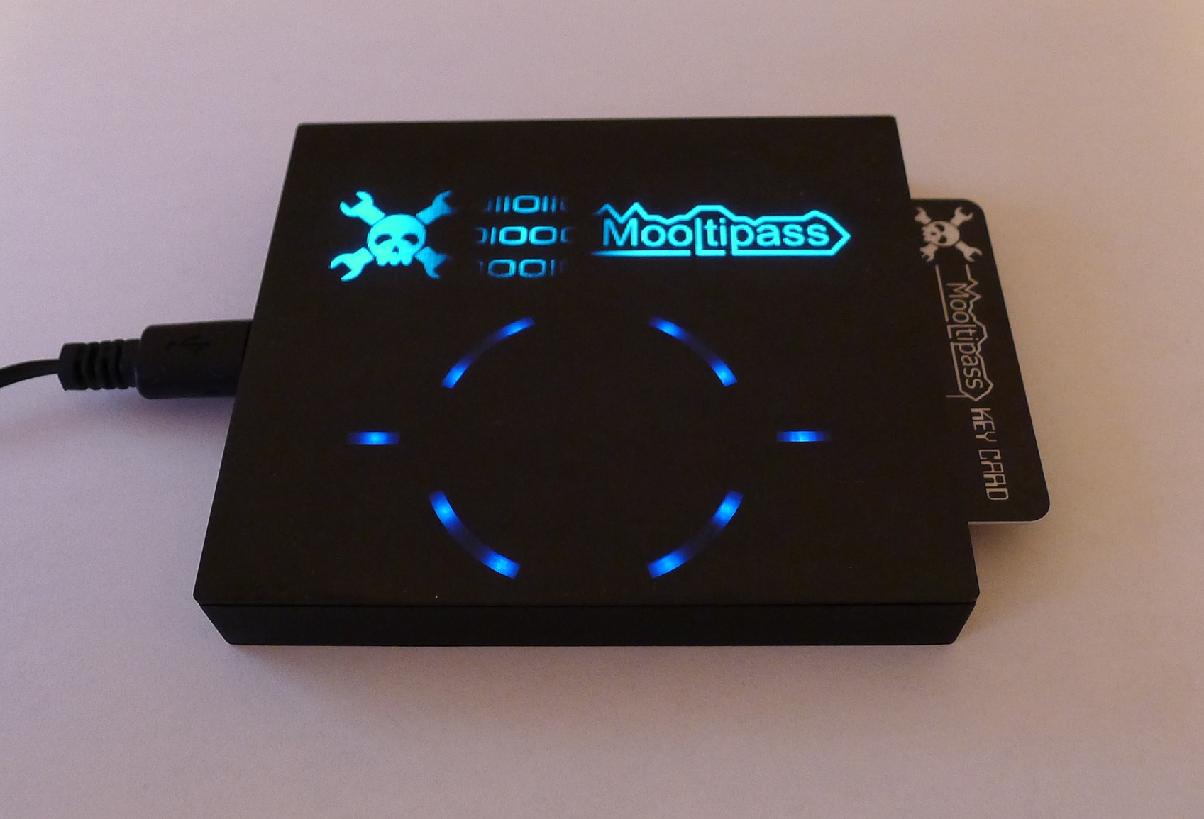
The last few weeks have been quite tense for the Mooltipass team as we were impatiently waiting for our smart cards, cases and front panels to come back from production. Today we received a package from China, so we knew it was the hour of truth. Follow us after the break if you have a good internet connection and want to see more pictures of the final product

Mooltipass final prototype

Continue reading “Developed On Hackaday: We Have Final Prototypes!”

OLED display, blue LED and Smartcard

Developed On Hackaday: Front Panels And Beta Testers Program

mooltipass front panel

We’re pretty sure that most of our readers already know it by now, but we’ll tell you anyway: the Hackaday community (writers and readers) is currently developing an offline password keeper, the Mooltipass. As it has been more than two weeks since we wrote an article about our progress, today’s will be about the Mooltipass front panels and our beta testers program.

At the end of our mechanical design rundown article we showed that we were originally planning to put a slightly tinted acrylic panel on top of our device. We however could still make out the Mooltipass’ insides, which wasn’t in line with the nice professional look we wanted. We then designed another front panel, one which was transparent above the OLED screen/LEDs and opaque (black) on top of the rest. To our surprise the result still wasn’t as good as we had hoped, as the contrast between the front panel and the screens/LEDs was too big. We finally came up with the panel shown above (see GitHub repository folder) which combines the two techniques previously described. As it is still in China, we’ll show you the final result when we get it in our hands.

We launched around 10 case prototypes in production, they will soon be shipped to our current contributors/advisers together with the smart cards chosen by Hackaday readers. In the meantime we sent our official call for beta testers to our mailing list recipients and hackaday.io followers, in which we asked them to fill a small form that will allow us to know them a bit better. We asked about their home/work computer setup, their level of expertise, their willingness to contribute to the prototype cost and finally specifics about who would use the Mooltipass they’d receive. We are targeting a broad range of users but also testers that will provide us with detailed feedback and clear bug reports.

We also spent quite a while searching for cheaper alternate parts that could be sourced in relatively big quantities. This is usually an overlooked aspect of a project so we preferred to tackle this as soon as possible. In a few weeks the contributors and I will receive all the components required to assemble our final prototype (front panels / case / top & bottom PCBs / smart cards) and it will be time to write a new update. Want to stay informed? You can join the official Mooltipass Google Group or follow us on Hackaday Projects.

Mini-Molder: Blow Molder Scratch-Built By Single Hacker

[youtube=https://www.youtube.com/watch?v=2P7MaZUrSQQ&w=580]


We caught up with [James Durand] at Maker Faire. He was one of the rare Makers (no mention of selling or future crowd funding) that had a booth at Maker Faire — he was exhibiting a blow molding machine that he built from scratch.

The fabrication process is 100% [James]. Every custom part was designed and milled by him. All of the assembly techniques were his to learn along the way. And we didn’t see anything that isn’t production ready. We’re both impressed and envious.

About three years ago he got the itch to build the mini-molder after learning about the Mold-A-Rama machine — a blow-molding vending machine that was popular a half century ago. A bit of his journey is documented as a molding category on his blog. For the most part it sounds like 1.5 years spent on the CAD design really paid off. He did share one element that required redesign. The initial prototype had a problem with the molds being pushed up when they came together. He tweaked the mechanism to close with a downward motion by flipping the hinge design. This seems to hold everything in place while the drinking fountain chiller and water pump cool the mold and the plastic model within.

Breaking Open The Quirky Nimbus

Nimbus

The Nimbus is a little Internet-connected device put out by a company called Quirky. It features four analog dials, each with graphic LCDs, with WiFi connectivity to show you how many tweets you’ve made in the past day. You know, in case you forgot, or something.

[Edu] didn’t find the social media-oriented Nimbus very useful, but Internet connected analog gauges are just so cool, so out came the screwdriver and the writing of new firmware commenced.

Inside the Nimbus there’s an SPI Flash, PIC micro, and an Electric Imp, a tiny ARM microcontroller and WiFi adapter stuffed inside an SD card. The Imp is always tied to a cloud service, in this case, a Quirky-lined cloud, but the folks at Quirky were keen to help [Edu] in his quest for better firmware.

After figuring out all the traces, [Edu] wrote a simple firmware that can control everything there is to control – the dials, displays, two buttons, and a speaker. So far he’s put some graphics on the display and PWM’d the theme from Monkey Island. This is just scratching the surface of what the device can do – [Edu] can still make use of the WiFi connectivity, and those dials can do much more than spin around in circles.

Monkey Island video below.

Continue reading “Breaking Open The Quirky Nimbus”