You take your air quality seriously, so shouldn’t your monitoring hardware? If you’re breathing in nasty VOCs or dust, surely a little blinking LED isn’t enough to express your displeasure with the current situation. Luckily, [Tobias Stanzel] has created the AqMood to provide us with some much-needed anthropomorphic environmental data collection.
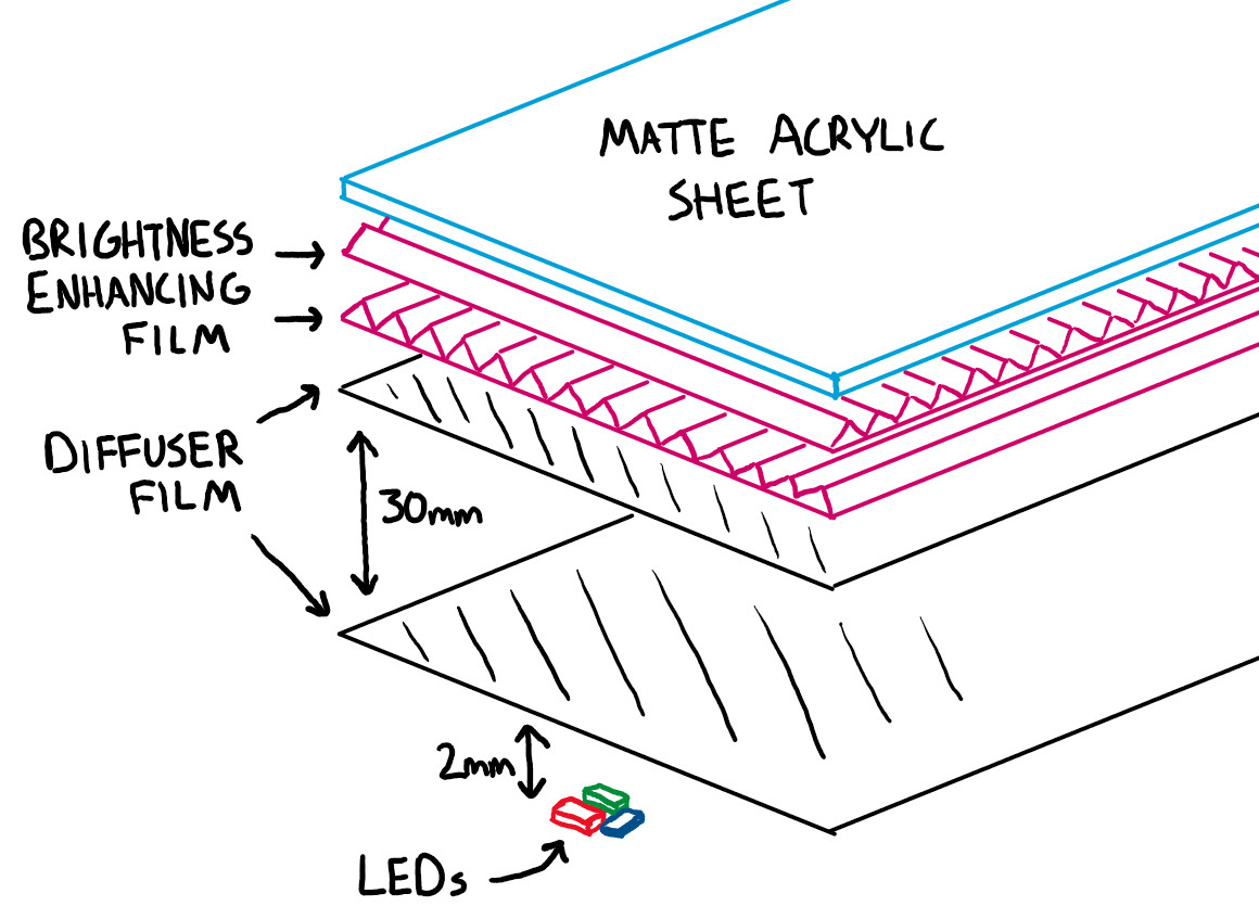
To be fair, the AqMood still does have its fair share of LEDs. In fact, one might even say it has several device’s worth of them — the thirteen addressable LEDs that are run along the inside of the 3D printed diffuser will definitely get your attention. They’re sectioned off in such a way that each segment of the diffuser can indicate a different condition for detected levels of particulates, VOCs, and CO2.
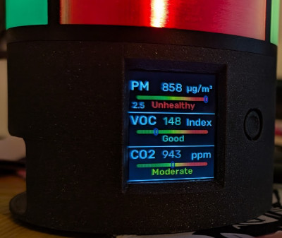 But what really makes this project stand out is the 1.8 inch LCD mounted under the LEDs. This display is used to show various emojis that correspond with the current conditions. Hopefully you’ll see a trio of smiley faces, but if you notice a bit of side-eye, it might be time to crack a window. If you’d like a bit more granular data its possible to switch this display over to a slightly more scientific mode of operation with bar graphs and exact figures…but where’s the fun in that?
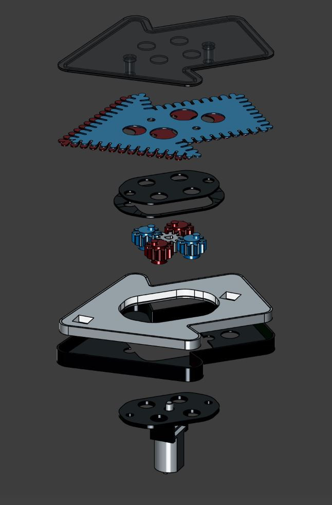
[Tobias] has not only shared all the files that are necessary to build your own AqMood, he’s done a fantastic job of documenting each step of the build process. There’s even screenshots to help guide you along when it’s time to flash the firmware to the XIAO Seeed ESP32-S3 at the heart of the AqMood.
If you prefer your air quality monitoring devices be a little less ostentatious, IKEA offers up a few hackable models that might be more your speed.