LED Strip And UC Add Some Flash To Your Tail Lights

[Dave] spiced up his new 2012 Nissan Juke with a little tail-light amendment. You can see that outlining the rim of the light enclosure is a series of dots. This is an LED strip that he added to augment the brake lights. It’s glued in place, and features side emitting LEDs so that the light will be focused behind the car.

To control the strip he’s using an ATtiny85 microcontroller. It’s the chip on the right, and an optoisolator next to it protects it from the 12V vehicle power which drives the strip (via a MOSFET), and acts as a trigger when the brake pedal is pressed. He wrote a few effects into the firmware. When the lights are turned on, the strip fades up to 75% over about eight seconds. When the brake pedal is pressed they go to 100%. Check out the video after the break (it seems a little weird to us, as the video runs 18 seconds but the audio keeps going… YMMV).

We’ve seen a couple of tail light concepts that flash the brake lights when you stomp on the pedal. Unfortunately the Juke (and all other cars as far as we know) don’t have functionality built-in to sense when you’ve really given the brake a sudden jolt. It makes us wonder if this info could be gleaned from the CANbus? Continue reading “LED Strip And UC Add Some Flash To Your Tail Lights”

RGB Upgrade For Ikea Single Color Fiber Optic Lamp

Five bucks will buy you a STRÅLA lamp from Ikea. It’s a battery operated hanging lamp that pipes the light out through multiple branches of fiber optic bundles. But you’ll only get white out of this, which is pretty boring. [Boris] decided to swap out the stock LED for an RGB unit and drive it with an Arduino.

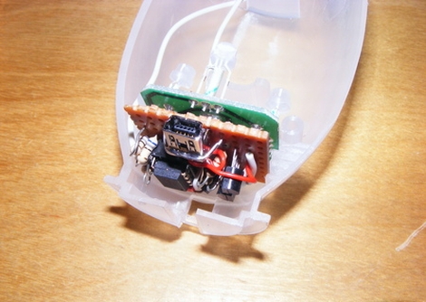
The lamp nucleus is just a couple of pieces of plastic which can be popped apart to reveal the shard of PCB hosting one LED. The body of that diode is flat on the top, and [Boris] filed down his replacement to match the form factor. There are only two conductors in the wire that runs between that PCB and the battery pack, so he replaced them with four conductors (R,G,B, and GND). His prototype uses the Arduino’s PWM capabilities to control the colors, but [Boris] recommends transitioning to a simple chip like a PIC 12F675 or one of the smaller ATtiny microcontrollers after you’ve got the bugs worked out.

See how this turned out in the clip after the break.

Continue reading “RGB Upgrade For Ikea Single Color Fiber Optic Lamp”

G-35 Christmas Lights Do Make A Great LED Matrix

This fully-addressable RGB LED matrix was built by [John Graham-Cummings]. He didn’t start from scratch, but wisely repurposed a strand of GE Color Effect lights and built a pleasant looking case in which to mount the G-35 hardware.

We’ve seen this hardware used in a similar way before. Because each ‘bulb’ has its own microcontroller, color data is shifted in via a serial bus. Orient the modules in any pattern you choose and account for that layout in software.

Since the strings have 50 bulbs, [John] simply cut off the one on the end to form his 7×7 matrix with the remaining 49 units. A square of plywood with a grid of holes holds each in place. Cord mess is not a problem as the extra was cut out and the remainders were soldered together again. [John] uses an Arduino Pro to feed in the data, which you can see for yourself in the clip after the break.

Continue reading “G-35 Christmas Lights Do Make A Great LED Matrix”

Controlling Shift Registers Via SPI

Hack a Day’s very own (and very prolific contributor) [Mike Szczys] put up a great tutorial on how to drive shift registers with an SPI interface.

[Mike]’s earlier tutorial of the 595 shift register goes through the functions of a shift register pin by pin. In a 595, bits for each position in the register are sent over one at a time. Most microprocessors have an Serial Peripheral Interface, and using an SPI bus means a lot less mucking about.

An ATmega168 was used for this build, although most Atmel chips can be made to work as an SPI master device. There are just three wires connecting the microcontroller to the shift register – SER, SRCLK, and RCLK. Like any other shift register setup, the build can be expanded by connecting the QH’ pin of the first 595 to the SER pin of the second.

[Mike] graciously made all the code for his build available. The video after the break is a 16-bit binary counter, a good stopping point before [Mike] rebuilds his Larson scanner/Cylon/Kitt, moving away from a PWM-based build to a register-based one.

Continue reading “Controlling Shift Registers Via SPI”

LED Sexting Belt Buckle

For some ungodly reason, [Scott] has a friend that wanted a ‘sexting themed’ Halloween costume. We won’t try to make any presumptions of the creativity or mental stability of [Scott]’s friend, but the SMS scrolling LED belt buckle he came up with is pretty cool.

The belt is based around a $13 scrolling LED belt buckle [Scott] found online. There was a problem with the belt buckle, though. Thirteen dollars means [Scott] didn’t get a whole lot of features with his buckle, so there are only 3 buttons on the entire device: letter up, letter down, and enter. Instead of pressing a button 80 times to get a lowercase ‘z,’ an Arduino was thrown into the mix to take care of all the button pressing.

The Arduino sketch could now input any message into the belt buckle in a matter of seconds. All that was left to do is taking care of the SMS to text part of the build. For this, [Scott] used the Sparkfun USB Host Shield and a custom Android app. Whenever an SMS is received on the phone, the message is sent through the USB shield to the Arduino and output on the belt buckle.

We won’t make any assumptions about the content of the messages during the Halloween party, but at least the video demo of the build is family friendly. Check it out after the break.

Continue reading “LED Sexting Belt Buckle”

Turning LEDs Into A Camera

[Udo] figured out how to turn a bunch of LEDs into a very low resolution camera.

The build is based around [Udo]’s Blinkenlight shield he’s been developing over the past year. The camera operates under the idea that there’s really not much difference between a LED and a photodiode; LEDs can do light emission and detection. In actuality, the LED ‘camera’ isn’t all that different from a linear CCD array, the type of image sensor in flatbed scanners.

After connecting his Blinkenlight shield to his Arduino and computer, [Udo] wrote a sketch that would capture 17 values from his LED camera. These values are shot over the serial connection where high levels of light show up as smaller numbers and low light levels are understood as larger numbers.

[Udo] has been doing a lot of other cool stuff with his Blinkenlight shield, like a persistence of vision experiment and pretending to be [Michael Knight]. Check out the video after the break for a demo of [Udo]’s linear LED camera.

Continue reading “Turning LEDs Into A Camera”

Wine-o-Meter Quantifies Your Bachelor Party Bad Behavior

wine_o_meter

[Phil] had a bunch of Shiftbrite modules set aside for an LED table project, but before he could get around to it, he decided to use them to build a prop for his friend’s bachelor party. Expecting plenty of drunken revelry, he constructed the Arduino Wine-o-Meter – a carnival “Test your strength” style breathalyzer.

The 25 Shiftbrite modules are lined up in a column, which is connected to an Arduino tucked away in a cardboard box. The Arduino takes readings from an MQ-3 Gas/Alcohol sensor was salvaged from another breathalyzer build [Phil] put together. While it has been noted in the past that this sensor is pretty inaccurate, it seems to serve his purposes quite well. Since his game is based on measuring the players’ blood alcohol content in relation to one another rather than obtaining an exact BAC reading, the poor calibration of the device should affect everyone equally.

It looks pretty cool, and we imagine that it will ensure that the party stays lively throughout the wee hours of the night. Check out the video below to see [Phil] walk you through a demo of his Wine-o-Meter.

Continue reading “Wine-o-Meter Quantifies Your Bachelor Party Bad Behavior”