Practical Guide To Pedal-Powered Electrical Generators

An adult human can produce about 100 Wh of mechanical power whilst cycling, which is a not inconsiderable amount if you can convert that to electricity with reasonable efficiency. In a recent article on EDN [T. K. Hareendran] goes over a few ways that you can turn the rotary motion of pedaling into usable electrical power.

Suggested voltage regulator for pedal-powered generator. (Credit: T. K. Hareendran, EDN)

A basic form of this is already widely deployed, in the form of a bicycle dynamo that is used to supply power to the front and rear lights. These typically put out something like 3 watts at 6 VAC, so with a simple bridge rectifier and some smoothing this can power a pretty bright LED or two. To get more out of it, you need to use a more capable generator, which can also be a brushed or brushless DC motor in a pinch, with ideally a flywheel in the whole contraption to balance out variations in the human power input.

As for the potential here, a commercial solution like the K-Tor Power Box 50 is specified for ‘greater than’ 50 Watt, with a nominal 12 VDC output. Its target market is emergency generators, with enough capability to keep phones, radios and flashlights charged. Considering the $435 asking price, there is probably quite a lot of DIY potential well within that price bracket, especially if you already have many of the requisite parts lying around.

Fortunately this is not a new idea, with us having covered using bicycles as well as gym equipment to generate electricity in the past.

Three stages of the dam construction

How To Convert A Drain Into A Hydropower Facility

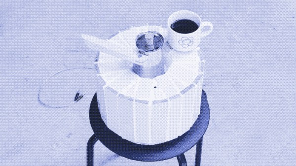
Over on his YouTube channel [Construction General] shows us how to convert a drain into a hydropower facility. This type of hydroelectric facility is known as a gravitation water vortex power plant. The central structure is a round basin which includes a central drain. The water feeds into the basin through a series of pipes which help to create the vortex which drives the water turbine before flowing out the drain.

To make the facility [Construction General] starts by laying some slabs as the foundation. One of the slabs has a hole to which the central drain pipe is attached. Bricks and mortar are then used to build the basin around the drain. A temporary central pipe is used for scaffolding along with some strings with hooks attached to hold the bricks and mortar in place for the basin. Integrated into the top half of the basin are fifteen inlet pipes which feed in water at an angle.

The next step is to build the dam wall. This is a bricks and mortar affair which includes the drain in the bottom of the wall and two spillways at the top. The spillways are for letting water flow out of the dam if it gets too full. Around the drainage in the dam wall a valve is installed. This valve is called the low-level outlet or the bottom outlet, and in this case it is a sluice, also known as a slide gate, which can be raised or lowered to control the rate of flow through the turbine.

Once the basin is complete and the low-level outlet is in place the scaffolding is removed. The basin is then painted, pink on the inside and white around the top. A turbine is constructed from various metal pieces and installed into the basin. The turbine is attached to a generator which is fixed atop the basin. The apparatus for operating the low-level outlet is installed and the dam is left to fill.

Hydropower is a topic we’ve covered here at Hackaday before, if you’re interested in the topic you might like to check out A Modest But Well-Assembled Home Hydropower Setup, Hydropower From A Washing Mashine, or Bicycle Hub Hydropower.

Continue reading “How To Convert A Drain Into A Hydropower Facility”

DIY Wind Turbine Gets A 3-Phase Rectifier

[Electronoobs] is using some brushless motors to make a DIY wind turbine. His recent video isn’t about the turbine itself, but a crucial electronic part: the three-phase rectifier. The reason it is so important is due to the use of brushless motors. Normal motors are not ideal for generating power for several reasons, as explained in the video below.

The brushless motors have three windings and generate three outputs, each out of phase with the others. You can’t just join them together because they are 120 degrees out of phase. But a special rectifier can merge the inputs efficiently and output a low-ripple DC voltage.

Continue reading “DIY Wind Turbine Gets A 3-Phase Rectifier”

3D Printing A Self-cleaning Water Filter

No one likes cleaning out water spouts. [NeedItMakeIt] wanted to collect rainwater and was interested in using a Coanda filter that those used on hydroelectric plants to separate out debris. Ultimately, he decided to design his own and 3D print it.

The design uses a sloping surface with teeth on it to coax water to go in one direction and debris to go in another. It fits into a typical spout, and seems like it works well enough. Some commenters note that varying volumes of rain and different types of debris behave differently, which is probably true. However, there are similar commercial products, so you’d guess there would be some value to using the technique.

The water pushes the debris off the slope, so you end up losing a little water with the debris. So as always, there’s a trade-off. You can see in the video that if the water flow isn’t substantial, the debris tends to stall on the slope. Could the filter be improved? That was the point in trying a second design.

It wasn’t a big improvement. That’s where there’s a plot twist. Well, actually, a literal twist. Instead of making a flat slope, the new design is a conic shape with a spiral channel. That improved flow quite a bit. We weren’t clear from the video of exactly where the debris was going with the last version.

Usually, when we think of the Coanda effect, we are thinking aerodynamics. It can be quite uplifting.

Continue reading “3D Printing A Self-cleaning Water Filter”

A filament extruder is shown on a workbench. On the front is a knob and the display of a PID controller. A black geared spool is mounted on the top of the extruder, and on the right, a clear plastic bottle is positioned over a metal rod.

Turning Waste Plastic Into Spools Of Filament

Despite being a readily-available source of useful plastic, massive numbers of disposable bottles go to waste every day. To remedy this problem (or take advantage of this situation, depending on your perspective) [Igor Tylman] created the PETmachine, an extruder to make 3D printer filament from PET plastic bottles.

The design of the extruder is fairly standard for such machines: a knife mounted to the frame slices the bottle into one long strip, which feeds through a heated extruder onto a spool which pulls the plastic strand through the system. This design stands out, though, in its documentation and ease of assembly. The detailed assembly guides, diagrams, and the lack of crimped or soldered connections all make it evident that this was designed to be built in a classroom. The filament produced is of respectable quality: 1.75 mm diameter, usually within a tolerance of 0.05 mm, as long as the extruder’s temperature and the spool’s speed were properly calibrated. However, printing with the filament does require an all-metal hotend capable of 270 ℃, and a dual-drive extruder is recommended.

One issue with the extruder is that each bottle only produces a short strand of filament, which isn’t sufficient for printing larger objects. Thus, [Igor] also created a filament welder and a spooling machine. The welder uses an induction coil to heat up a steel tube, inside of which the ends of the filament sections are pressed together to create a bond. The filament winder, for its part, can wind with adjustable speed and tension, and uses a moving guide to distribute the filament evenly across the spool, avoiding tangles.

If you’re interested in this kind of extruder, we’ve covered a number of similar designs in the past. The variety of filament welders, however, is a bit more limited.

Thanks to [RomanMal] for the tip!

Solar Light? Mains Light? Yes!

So you want a light that runs off solar power. But you don’t want it to go dark if your batteries discharge. The answer? A solar-mains hybrid lamp. You could use solar-charged batteries until they fall below a certain point and then switch to mains, but that’s not nearly cool enough. [Vijay Deshpande] shows how to make a lamp that draws only the power it needs from the mains.

The circuit uses DC operation and does not feed power back into the electric grid. It still works if the mains is down, assuming the solar power supply is still able to power the lamp. In addition, according to [Vijay], it will last up to 15 years with little maintenance.

The circuit was developed in response to an earlier project that utilized solar power to directly drive the light, when possible. If the light was off, the solar power went to waste. Also, if the mains power failed at night, no light.

The answer, of course, is to add a battery to the system and appropriate switching to drive the lights or charge the battery and only draw power from the mains when needed. Since the battery can take up the slack, it becomes easier to load balance. In periods of low sunlight, the battery provides the missing power until it can’t and then the mains supply takes over.

Comparators determine whether there is an under-voltage or over-voltage and use this information to decide whether the battery charges or if the main supply takes over. Some beefy MOSFETs take care of the switching duties. Overall, a good way to save and reuse solar cell output while still drawing from the grid when necessary.

Small solar lights don’t take much, but won’t draw from commercial power. Solar “generators” are all the rage right now, and you could probably adapt this idea for that use, too.

Caltech Scientists Make Producing Plastics From CO2 More Efficient

For decades there has been this tantalizing idea being pitched of pulling CO2 out of the air and using the carbon molecules for something more useful, like making plastics. Although this is a fairly simple process, it is also remarkably inefficient. Recently Caltech researchers have managed to boost the efficiency somewhat with a new two-stage process involving electrocatalysis and thermocatalysis that gets a CO2 utilization of 14%, albeit with pure CO2 as input.

The experimental setup with the gas diffusion electrode (GDE) and the copolymerization steps. (Credit: Caltech)

The full paper as published in Angewandte Chemie International is sadly paywalled with no preprint available, but we can look at the Supplemental Information for some details. We can see for example the actual gas diffusion cell (GDE) starting on page 107 in which the copper and silver electrodes react with CO2 in a potassium bicarbonate (KHCO3) aqueous electrolyte, which produces carbon monoxide (CO) and ethylene (C2H4). These then react under influence of a palladium catalyst in the second step to form polyketones, which is already the typical way that these thermoplastics are created on an industrial scale.

The novelty here appears to be that the ethylene and CO are generated in the GDEs, which require only the input of CO2 and the potassium bicarbonate, with the CO2 recirculated for about an hour to build up high enough concentrations of CO and C2H4. Even so, the researchers note a disappointing final quality of the produced polyketones.

Considering that a big commercial outfit like Novomer that attempted something similar just filed for Chapter 11 bankruptcy protection, it seems right to be skeptical about producing plastics on an industrial scale, before even considering using atmospheric CO2 for this at less than 450 ppm.