You Can Have My TIPs When You Pry Them From My Cold, Dead Hands

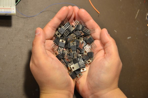
We’ve seen a growing number of posts and recommendations around the net regarding components, specifically transistors. “Don’t use old parts” they cry,  “Go with newer components.”  You can often find these recommendations on Arduino forums. This all came to a head with a page called “Do Not TIP,” which was linked in the Arduino subreddit.  This page belongs to [Tom Jennings], creator of Fidonet, and one of the early authors of what would become Phoenix BIOS. [Tom] and a few others have been calling for everyone to send their old parts to the landfill – not use them, nor gift them to new experimenters. Get them out of the food chain. No offense to [Tom], but we have to disagree. These parts are still perfectly usable for experienced designers, and have a lot to offer new hardware hackers.

TIP is the part number prefix for a series of power transistors created by Texas Instruments.  In fact, “TIP” stands for Texas Instruments Power. The series was originally released in 1969. Yes, that’s right, 1969. Why are we still using parts designed when man first walked on the moon? The same reason people are still using the 555 timer: they’re simple, they’re easily available, they’re robust, and most of all, they get the job done. The TIP series has been used in thousands of classes, tutorials both online and off, and millions of projects over the years. Much of that documentation is already out there on the internet. The TIP series is also out in the distribution channel – they’ve been used for 40 years. Any retail shop that stocks a few electronics parts will have at least one of the TIP series.

The TIP series aren’t always the best transistors for the job. However, for most hobbyist-designed circuits, we don’t need the best performance, nor the best price – we’re going to use the parts we have on hand. There is always room to improve once you get the basic circuit working.

Continue reading “You Can Have My TIPs When You Pry Them From My Cold, Dead Hands”

Becoming A State Machine Design Mastermind

Imagine a robot with an all-around bump sensor. The response to the bump sensor activating depends on the previous state of the robot. If it had been going forward, a bump will send it backwards and vice versa. This robot exhibits behavior that is easy to model as a state machine. That is, the outputs of the machine (motor drive) depend not only on the inputs (the bump sensor) but also on the current state of the machine (going forward or backward).

As state machines go, that’s not an especially complicated one. Many state machines have lots of states with complex conditions. For example, consider a phone switchboard. The reaction to a phone going off hook depends on the state of the line. If the state is ringing, picking up the phone makes a connection. If the state is idle, the phone gets a dial tone. The switchboard also has to have states for timeouts, connection failures, three way calling, and more.

If you master state machines your design and debug cycles will both move along faster. Part of this is understanding and part is knowing about the tools you can choose to use. I’ll cover both below.

Continue reading “Becoming A State Machine Design Mastermind”

Alcove: Blinky Art With A Killer Story

We should come clean right up front. We like blinky stuff, tech art, smoke machines, and dark atmospheric electronic music. This audiovisual installation piece (scroll down) by [supermafia] ticks off all our boxes. As the saying doesn’t really go, writing about site-specific audiovisual art pieces is like dancing about architecture, so go ahead and watch the video (Vimeo) below the break.

Continue reading “Alcove: Blinky Art With A Killer Story”

Self Built Power Meter Uses Dual Sense Transformers

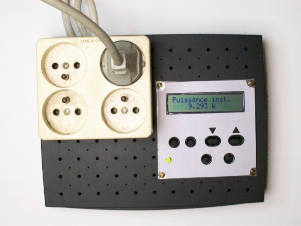
[Renaud] built a AC power meter from scratch. While commercial power meters like the Kill A Watt are available [Renaud’s] build gives an interesting insight into the methods used.

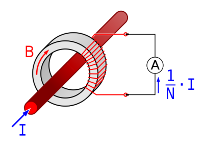
currentAt the heart of [Renaud’s] design lie two sense transformers. The first is a typical voltage stepdown transformer. This brings the AC line voltage down to +/- 10V, which is more amenable to digital sampling. The second is a current sense transformer. In current transformers the primary is typically a single wire (the AC line in this case) passing through the middle of a ring (see the picture to the right from wikipedia). The secondary is wrapped round the ring. When the secondary coil is shorted a current in the primary wire/coil induces a current in the secondary coil.

In practice, the voltage drop across a low value resistor is used to detect the current in the secondary. Clamp meters use this principle to make non-contact current measurements. Other power meters often use hall effect sensors for current measurements. It will be interesting to see how these methods compare when [Renaud] benchmarks this build.

[Renaud] takes the voltage and current readings from these transformers and samples them with a PIC in order to calculate power. As the AC voltage is periodic [Renaud] uses a method similar to Equivalent Time Sampling (ETS) to combine waveforms from multiple cycles and increase the effective sample rate.

Great stuff [Renaud]!

Building A Dead-On-Accurate Model Ford Pickup From Scratch

In a world filled with 3D printed this and CNC machined that, it’s always nice to see someone who still does things the old-fashioned way. [Headquake137] built a radio controlled truck body (YouTube link) from wood and polystyrene using just a saw, a Dremel, a hobby knife, and a lot of patience. This is one of those builds that blurs the lines between scale model and sculpture. There aren’t too many pickup trucks one might call “iconic” but if we were to compile a list, the 6th generation Ford F-series would be on it. [Headquake137’s] model is based on a 1977 F100.

ford-thumb2The build starts with the slab sides of the truck. The basic outline is cut into a piece of lumber which is then split with a handsaw to create a left and a right side. From there, [Headquake137’s] uses a Dremel to carve away anything that doesn’t look like a 1977 F100. He adds pieces of wood for the roof, hood, tailgate, and the rest of the major body panels. Small details like the grille and instrument panel are created with white polystyrene sheet, an easy to cut material often used by train and car modelers.

When the paint starts going on, the model really comes to life. [Headquake137] weathers the model to look like it’s seen a long life on the farm. The final part of the video covers the test drive of the truck, now mounted to a custom chassis. The chassis is designed for trails and rock crawling, so it’s no speed demon, but it sure does look the part riding trails out in the woods!

[Headquake137] managed to condense what must have been a 60 or 70 hour build down to a 14 minute video found below.

Continue reading “Building A Dead-On-Accurate Model Ford Pickup From Scratch”

Hacker Reads Magnetic Stripe Card With Flatbed Scanner

[anfractuosus] has been reading magnetic stripe card… optically!

While hackers routinely read and write stripe cards, this is the first time we’ve reported on optically imaging and decoding data from the magnetic stripe. [anfratuosus] used a magnetic developer which is designed to allow visual inspection of the magnetic stripe. The developer uses micron sized iron particles in a suspension which are dropped onto the stripe. To the particles, the magnetic stripe looks like a series of magnets lined up. Long magnets striperepresent 0s and short magnets 1s. With each bit the orientation of the magnet changes, something like the diagram to the right. The magnetic field is strongest where the poles meet. So the iron particles are attracted to these flux reversal points on the stripe creating a visible pattern . There’s an awesome video of the process in action below.

While magnetic developer was designed for debugging faulty recording systems [anfratuosus] went a step further scanning the “developed” card, and writing a tool to decode the images and extract the card data. [anfratuosus] doesn’t mention any particular application, we love this circuitous hack anyway!

Continue reading “Hacker Reads Magnetic Stripe Card With Flatbed Scanner”

Visualizing RF Standing Waves

Standing waves are one of those topics that lots of people have a working knowledge of, but few seem to really grasp. A Ham radio operator will tell you all about the standing wave ratio (SWR) of his antenna, and he may even have a meter in the shack to measure it. He’ll know that a 1.1 to 1 SWR is a good thing, but 2 to 1 is not so good. Ask him to explain exactly what a standing wave is, though, and chances are good that hands will be waved. But [Allen], a Ham also known as [W2AEW], has just released an excellent video explaining standing waves by measuring signals along an open transmission line.

[Source: Wikipedia]
[Source: Wikipedia]
To really understand standing waves, you’ve got to remember two things. First, waves of any kind will tend to be at least partially reflected when they experience a change in the impedance of the transmission medium. The classic example is an open circuit or short at the end of an RF transmission line, which will perfectly reflect an incoming RF signal back to its source. Second, waves that travel in the same medium overlap each other and their peaks and troughs can be summed. If two waves peak together, they reinforce each other; if a peak and a trough line up, they cancel each other out.

Continue reading “Visualizing RF Standing Waves”