There was a time when only the richest ham radio operators could have a radio with a panadapter. Back in the day, this was basically a spectrum analyzer that monitored a broad slice of the receiver’s intermediate frequency so you could see signals on either side of the receiver’s actual frequency. Today, with SDR technology and computers, this is an easy thing for receivers to implement. But what if you want to refit a classic radio? It isn’t that hard, and [Mirko Pavleski] shares his notes on how he tackled the project. You can also check it out in the video below.
The plan is simple. A FET amplifier taps the radio’s IF stage before the first IF filter. This provides good isolation and buffering. Then, an emitter follower stage provides a matched output to the SDR through a low-pass filter. The SDR remains tuned to the IF frequency, of course. The rest is essentially software and procedures.
Meshtastic has been experiencing a bit of a renaissance lately, as the off-grid, long-range radio text messaging protocol gains a ton of new users. It’s been used to create mesh networks in cities, during disasters and protests, in small groups while hiking or camping, and for search and rescue operations. Although it’s connected plenty of people together in all of these ways, [GreatScott!] wanted to put it to work connecting some computing resources instead. He has a garden shed that’s too far for WiFi, so Meshtastic was used to connect it instead.
This isn’t a project to bring broadband Internet out to the shed, though; Meshtastic is much too slow for that. All he really wanted to do here was to implement a basic alarm system that would let him know if someone had broken in. The actual alarm triggering mechanism is an LED emitter-detector pair installed in two bars, one of which sends a 12V signal out if the infrared beam from the other is broken. They’re connected to a Heltec ESP32 LoRa module which is set up to publish messages out on the Meshtastic communications channel. A second module is connected to the WiFi at the house which is communicates with his Home Assistant server.
Integrating Meshtastic devices into Home Assistant can be pretty straightforward thanks to the various integrations already available, but there is some configuration to get these specific modules working as an alarm. One of the pins on the remote module had to be set up to watch the light bar, and although sending the alarm message out when this triggered worked well, the received signal never passed through to Home Assistant until [GreatScott!] switched to using the RadioLib library an an MQTT integration instead. But with perhaps more configuration than he planned for out of the way, [GreatScott!]’s alarm is up and running. Meshtastic projects often balloon into more than we had originally planned though, in more ways than one. You can follow along as our own [Tom Nardi] attempts to connect all of New Jersey with this new protocol.
Antenna design is often referred to as a black art or witchcraft, even by those experienced in the space. To that end, [Janne] wondered—could years of honed skill be replaced by bruteforcing the problem with the aid of some GPUs? Iterative experiments ensued.
[Janne]’s experience in antenna design was virtually non-existent prior to starting, having a VNA on hand but no other knowledge of the craft. Formerly, this was worked around by simply copying vendor reference designs when putting antennas on PCBs. However, knowing that sometimes a need for something specific arises, they wanted a tool that could help in these regards.
The root of the project came from a research paper using an FDTD tool running on GPUs to inversely design photonic nanostructures. Since light is just another form of radio frequency energy, [Janne] realized this could be tweaked into service as an RF antenna design tool. The core simulation engine of the FDTD tool, along with its gradient solver, were hammered into working as an antenna simulator, with [Janne] using LLMs to also tack on a validation system using openEMS, an open-source electromagnetic field solver. The aim was to ensure the results had some validity to real-world physics, particularly important given [Janne] left most of the coding up to large language models. A reward function development system was then implemented to create antenna designs, rank them on fitness, and then iterate further.
The designs produced by this arcane system are… a little odd, and perhaps not what a human might have created. They also didn’t particularly impress in the performance stakes when [Janne] produced a few on real PCBs. However, they do more-or-less line up with their predicted modelled performance, which was promising. Code is on Github if you want to dive into experimenting yourself. Experienced hands may like to explore the nitty gritty details to see if the LLMs got the basics right.
We’ve featured similar “evolutionary” techniques before, including one project that aimed to develop a radio. If you’ve found ways to creatively generate functional hardware from boatloads of mathematics, be sure to let us know on the tipsline!
[GreatScott] has recently been tinkering in the world of radio frequency emissions, going so far as to put their own designs in a proper test chamber to determine whether they meet contemporary standards for noise output. This led them to explore the concept of shielding, and how a bit of well-placed metal can make all the difference in this regard.
The video focuses on three common types of shielding—absorber sheets, shielding tapes, and shielding cabinets. A wide variety of electronic devices use one or more of these types of shielding. [GreatScott] shows off their basic effectiveness by putting various types of shielding in between a noise source and a near-field probe hooked up to a receiver. Just placing a bit of conductive material in between the two can cut down on noise significantly. Then, a software defined radio (SDR) was busted out for some more serious analysis. [GreatScott] shows how Faraday cages (or simple shielding cabinets] can be used to crush down spurious RF outputs to almost nothing, and how his noisy buck-boost designs can be quieted down with the use of the right absorber sheets that deal well with the problematic frequencies in question. The ultimate upshot of the tests is that higher frequencies respond best to conductive shielding that is well enclosed, while lower frequency noise benefits from more absorptive shielding materials with the right permeability for the job.
Shielding design can be a complex topic that you probably won’t master in a ten minute YouTube video, but this content is a great primer if you’re new to the topic. We’ve covered the topic before, too, particularly on how a bit of DIY shielding can really aid a cheap SDR’s performance. Video after the break.
For as long as small, hidden radio transmitters have existed, people have wanted a technology to detect them. One of the more effective ways to find hidden electronics is the nonlinear junction detector, which illuminates the area under investigation with high-frequency radio waves. Any P-N semiconductor junctions in the area will emit radio waves at harmonic frequencies of the original wave, due to their non-linear electronic response. If, however, you suspect that the electronics might be connected to a dangerous device, you’ll want a way to detect them from a distance. One solution is harmonic radar (also known as nonlinear radar), such as this phased-array system, which detects and localizes the harmonic response to a radio wave.
One basic problem is that semiconductor devices are very rarely connected to antennas optimized for the transmission of whatever harmonic you’re looking for, so the amount of electromagnetic radiation they emit is extremely low. To generate a detectable signal, a high-power transmitter and a very high-gain receiver are necessary. Since semiconductor junctions emit stronger lower harmonics, this system transmits in the 3-3.2 GHz range and only receives the 6-6.4 GHz second harmonic; to avoid false positives, the transmitter provides 28.8 decibels of self-generated harmonic suppression. To localize a stronger illumination signal to a particular point, both the transmit and receive channels use beam-steering antenna arrays.
In testing, the system was able to easily detect several cameras, an infrared sensor, a drone, a walkie-talkie, and a touch sensor, all while they were completely unpowered, at a range up to about ten meters. Concealing the devices in a desk drawer increased the ranging error, but only by about ten percent. Even in the worst-case scenario, when the system was detecting multiple devices in the same scene, the ranging error never got worse than about 0.7 meters, and the angular error was never worse than about one degree.
For a refresher on the principles of the technology, we’ve covered nonlinear junction detectors before. While the complexity of this system seems to put it beyond the reach of amateurs, we’ve seen some equally impressive homemade radar systems before.
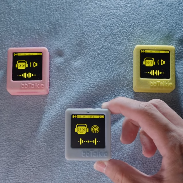
Walkie-talkies are great fun, and [RealCorebb]’s bbTalkie project takes the concept a step further by adding some extremely cool features to make a highly refined, self-contained ESP32-based communicator. bbTalkie completely does away with a push-to-talk button by implementing robust voice detection that works reliably even in noisy environments. It was all designed with cycling in mind, so hands-free operation that stands up to noise is a big plus.
Hands-free, wireless, self-contained digital walkie-talkies that can connect in a group. What’s not to like?
The core of communication is done over ESP-NOW, which is Espressif’s own protocol for direct device-to-device broadcasting. This removes the need to involve any sort of external service like SIM cards or internet access to transmit voice. Performance is best with an external antenna, naturally, but ESP-NOW doesn’t actually require anything other than the existing on-board hardware.
Because volume-based automatic triggers are highly susceptible to noise, voice detection is done with the help of VADNet, a neural network-based model implemented locally on the device. This system can reliably detect human speech, even in noisy environments. This lets bbTalkie switch between transmit and listen modes automatically and hands-free, without false triggers.
Even when doing all that, there’s still spare capability to play with. Further to the goal of making bbTalkie useful for cyclists in a group, [RealCorebb] added a system that can recognize specific voice commands (like “turn left” for example, or “wait for me!”) which trigger synchronized animations to play on the displays of all connected units. There’s even some experimental support for controlling a camera over Bluetooth, though currently it only supports hardware from Sony.
Watch a tour of it in the video below (Chinese language, English captions available). The OLED screens and animations are adorable, and are great visual feedback of what the unit is doing at any given moment.
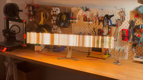
When it comes to electromagnetic waves, humans can really only directly perceive a very small part of the overall spectrum, which we call “visible light.” [rootkid] recently built an art piece that has perception far outside this range, turning invisible waves into a visible light sculpture.
The core of the device is the HackRF One. It’s a software defined radio (SDR) which can tune signals over a wide range, from 10 MHz all the way up to 6 GHz. [rootkid] decided to use the HackRF to listen in on transmissions on the 2.4 GHz and 5 GHz bands. This frequency range was chosen as this is where a lot of devices in the home tend to communicate—whether over WiFi, Bluetooth, or various other short-range radio standards.
The SDR is hooked up to a Raspberry Pi Zero, which is responsible for parsing the radio data and using it to drive the light show. As for the lights themselves, they consist of 64 filament LEDs bent into U-shapes over a custom machined metal backing plate. They’re controlled over I2C with custom driver PCBs designed by [rootkid]. The result is something that looks like a prop from some high-budget Hollywood sci-fi. It looks even better when the radio waves are popping and the lights are in action.