Time was once that the amateur radio bands were an aurally predictable place. Spinning the dial up and down the bands, one heard familiar sounds – the staccato of Morse, the [Donald Duck] of sideband voice transmissions, and the occasional flute-like warble of radioteletype signals. Now, the ham bands are full of exotic signals encoding all manner of digital signals, each one with a unique sound and unique demodulation needs. What’s a ham to do?
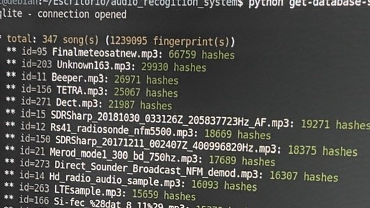
Help is on the way. [José Carlos Rueda] has made progress toward automatically classifying unknown signals by modifying a Shazam-like app. Shazam is a popular smartphone app that listens to a few seconds of a song, creates an audio fingerprint of it, and searches a massive database of songs for a match. [Rueda] used a homebrew version of the app to search a SQL-lite database of audio fingerprints populated not with a playlist of popular music, but with samples from every known signal type in the Signal Identification Wiki. The database contains hashes for an FFT of each sample, which can be easily searched. With a five to ten second sample of a signal, captured either live over a microphone or from a recording, he is able to identify the signal automatically.
Whether it be the weird, dissonant wail of PSK-31 or the angry buzzing of PACTOR, the goings-on across the bands no longer have to remain a mystery. We really like the idea here, and wonder if it can be expanded upon to visually decode signals based on their waterfall signatures using TensorFlow. There are some waterfall examples in [Danie Conradie]’s excellent article on RF modulation that could get you started.
[via RTL-SDR.com]