Let me throw in a curveball—watching your 3D print fail in real-time is so much more satisfying when you have a crisp, up-close view of the nozzle drama. That’s exactly what [Mellow Labs] delivers in his latest DIY video: transforming a generic HD endoscope camera into a purpose-built nozzle cam for the Prusa Mini. The hack blends absurd simplicity with delightful nerdy precision, and comes with a full walkthrough, a printable mount, and just enough bad advice to make it interesting. It’s a must-see for any maker who enjoys solder fumes with their spaghetti monsters.
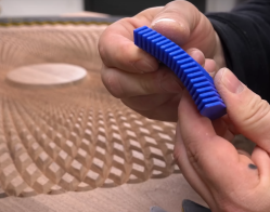
What makes this build uniquely brilliant is the repurposing of a common USB endoscope camera—a tool normally reserved for inspecting pipes or internal combustion engines. Instead, it’s now spying on molten plastic. The camera gets ripped from its aluminium tomb, upgraded with custom-salvaged LEDs (harvested straight from a dismembered bulb), then wrapped in makeshift heat-shrink and mounted on a custom PETG bracket. [Mellow Labs] even micro-solders in a custom connector just so the camera can be detached post-print. The mount is parametric, thanks to a community contribution.
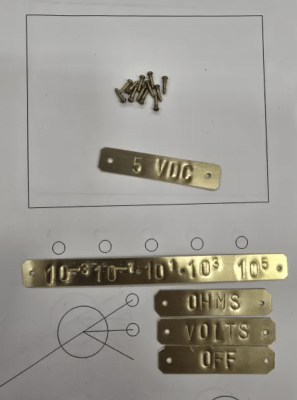
This is exactly the sort of hacking to love—clever, scrappy, informative, and full of personality. For the tinkerers among us who like their camera mounts hot and their resistor math hotter, this build is a weekend well spent.